Hi all,
I've been meaning to start this thread for a long while - as a forum for learning, and documentation of my own work over the past several years to design and create a very good field coil loudspeaker.
A little about me first, and some history on my project. In college I studied drawing and sculpture, and eventually graduated in visual design. For 20+ years since I've worked as a software developer. I've never enjoyed engineering other than as a means to an end. I don't enjoy mathematics at all. I know little (however, no longer nothing) of the actual physics behind a good sounding speaker.
To stand any chance in this, my philosophy has been just as it was when I entered software with a fine art background and no CS degree. I've hoped that with just creativity, a passion for craftsmanship and an understanding of a handful of very basic technical concepts... it is in fact possible to come up with something wonderful. I hope that speaks to some of you, too. We'll see.
A few of my basic design principles were these:
I started daydreaming about this about 5 years ago, and a year later had started posting work occasionally over here. I owe a huge debt of gratitude to Stefan and many others who contributed to that thread for my own basic knowledge of drivers and of design considerations around field coils specifically.
I copied one of Stefan's early designs for my own first motors, 8 Ohms and about 1.5T in the gap. 18AWG wire, about 1475 winds, high performance epoxy between each layer.
This is the point where many of you may drop off this thread - it was very costly to make them - about $1600 for a local company to mill out the steel and $180 for the copper wire. It was worth it to me at the time, though - I used that first pair for years to produce prototypes and test ideas. Endless experimenting. Lots of failures, and a few big successes. In short, worth every penny.
50 or more handmade cones and half a dozen spiders and surrounds later, this was the first driver that sounded quite good...
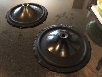
Basket:

Spider:

Ready to trim waste material:

Playing a song for the first time:
http://kensonger.com/drivers_v1.html
As impressive as they sounded in person, they had a few fatal flaws. The 8 Ohm motor got too hot after a few hours of use. Nothing dangerous of course, but with a 1mm gap and a washi paper former it didn't seem wise to expect that rubbing or deformation of the voice coil wouldn't occur eventually with years of hard use. The wooden frame was cool looking imho, but not durable or structurally rigid enough. The surrounds were laughably over-large. And, the silk spider was magnificent initially but eventually wore down and began to sag after a couple hundred hours of use.
Encouraged by the progress however, I decided to sink most of my annual bonus that year into designing and milling four sets of an improved motor design - still expensive, but significantly cheaper per unit. In FEMM, that design looked like this:

Minor tweaks after that screenshot got me up to a little over 1.6T in the gap. Not too bad. I had the first aluminum and brass frame design parts water-jet cut (which was pretty affordable really). Here was the metal on the happy day it had all arrived:

Alright, that seems like a pretty good start. If anyone is curious about something specific please feel free to ask - and, if this kind of chronology isn't interesting or educational to follow please do let me know - I'm happy to shift toward what is of interest and most useful. More soon.
I've been meaning to start this thread for a long while - as a forum for learning, and documentation of my own work over the past several years to design and create a very good field coil loudspeaker.
A little about me first, and some history on my project. In college I studied drawing and sculpture, and eventually graduated in visual design. For 20+ years since I've worked as a software developer. I've never enjoyed engineering other than as a means to an end. I don't enjoy mathematics at all. I know little (however, no longer nothing) of the actual physics behind a good sounding speaker.
To stand any chance in this, my philosophy has been just as it was when I entered software with a fine art background and no CS degree. I've hoped that with just creativity, a passion for craftsmanship and an understanding of a handful of very basic technical concepts... it is in fact possible to come up with something wonderful. I hope that speaks to some of you, too. We'll see.
A few of my basic design principles were these:
- the motor should perform well on 12VDC
- the motor must not overheat, and must be as strong as possible
- the moving mass must be as light and stiff as possible
- the suspension must be as soft as possible
- the driver response must be acceptably full range
- there is some opportunity to innovate upon spider designs
I started daydreaming about this about 5 years ago, and a year later had started posting work occasionally over here. I owe a huge debt of gratitude to Stefan and many others who contributed to that thread for my own basic knowledge of drivers and of design considerations around field coils specifically.
I copied one of Stefan's early designs for my own first motors, 8 Ohms and about 1.5T in the gap. 18AWG wire, about 1475 winds, high performance epoxy between each layer.
This is the point where many of you may drop off this thread - it was very costly to make them - about $1600 for a local company to mill out the steel and $180 for the copper wire. It was worth it to me at the time, though - I used that first pair for years to produce prototypes and test ideas. Endless experimenting. Lots of failures, and a few big successes. In short, worth every penny.
50 or more handmade cones and half a dozen spiders and surrounds later, this was the first driver that sounded quite good...
Basket:
Spider:
Ready to trim waste material:
Playing a song for the first time:
http://kensonger.com/drivers_v1.html
As impressive as they sounded in person, they had a few fatal flaws. The 8 Ohm motor got too hot after a few hours of use. Nothing dangerous of course, but with a 1mm gap and a washi paper former it didn't seem wise to expect that rubbing or deformation of the voice coil wouldn't occur eventually with years of hard use. The wooden frame was cool looking imho, but not durable or structurally rigid enough. The surrounds were laughably over-large. And, the silk spider was magnificent initially but eventually wore down and began to sag after a couple hundred hours of use.
Encouraged by the progress however, I decided to sink most of my annual bonus that year into designing and milling four sets of an improved motor design - still expensive, but significantly cheaper per unit. In FEMM, that design looked like this:
Minor tweaks after that screenshot got me up to a little over 1.6T in the gap. Not too bad. I had the first aluminum and brass frame design parts water-jet cut (which was pretty affordable really). Here was the metal on the happy day it had all arrived:
Alright, that seems like a pretty good start. If anyone is curious about something specific please feel free to ask - and, if this kind of chronology isn't interesting or educational to follow please do let me know - I'm happy to shift toward what is of interest and most useful. More soon.
Last edited:
Hi Ken,
thanks for taking your time! A pleasant read, and I´m certainly looking forward to see, read and learn.
All the best
Mattes
thanks for taking your time! A pleasant read, and I´m certainly looking forward to see, read and learn.
All the best
Mattes
Hey Mattes! Really enjoyed your most recent email - you're doing such refined work, and the design idea you're exploring looks very promising. I'll shoot you a reply soon.
Mr. Fahey! Thank you for the kind words, good to see you. You've played a part in my effort too, you know. After reading your posts on the topic of voice coils, I bought a 14" scrap length of 36mm chrome-plated steel bar from a local warehouse and have made all of my voice coils with it per your advice. It's a part of a very simple winding assembly - I wrap it with thin layers of nomex to a .2mm thickness, and then wet-form a long voice coil former 'blank' around the entire length. After it dries and I've wound 6-8 voice coils, the nomex slides off the polished chrome beautifully, and it's easy to discard the nomex from the inside of each washi former after trimming them to size. Perfect results, every single time.
I'd like to take a minute to offer a couple of general recommendations to anyone who feels inspired to make a driver.
For starters, model absolutely everything in software first. Whatever I have produced, no matter how trivial, was first designed and validated in a digital space. That's saved me personal shame and money over the years, in not having had to discover assembly problems and somehow work around them. We all make mistakes - you certainly don't want to pay for any of them when milling steel and working with other expensive materials, or in trying to finally assemble a driver with very fine tolerances. Don't make guesses if you can help it, always know in advance. Fusion 360 is free to little people like you and me, it's very powerful, and the learning curve is small.
Secondly, buy a 3D printer. I wish I had sooner than a year into my work. Or, you know... buy two of them, both an SLA and FDM if you can afford to. Creality makes large format FDM printers on the cheap. My CR-10 has been essential for producing cone molds, bobbins, jigs and guides. The SLA resin printer has conversely been great for actual components, where a very high level of accuracy and finish is important.
Anyhow, after listening to the first viable driver I bought a copy of DATS. If you don't know it, that's a small piece of hardware from Dayton Audio that connects to a computer and a driver. With the click of a button it allows accurate T/S measurements to be taken. The driver measured like this:
SPL: 94.36 dB
R(e): 9.216
F(s): 19.51
Q(ts): 0.2242
Q(es): 0.2389
Q(ms): 3.656
L(e), 10k / 1k: 0.4473 / 0.9154
M(md): 17.5 grams
M(ms): 22.5 grams
V(as): 20.05 cubic feet (567.8 liters)
I eventually came to understand that low Qts might be a design challenge, and that Le was probably too high to reproduce the entire last octave. More on that later. I didn't at the time have a quality microphone to take response measurements, and didn't know free software like REW was available if I had. I also was hesitant back then to see too many objective results - that may have been a good thing. Response was probably disappointing at the time, and had I seen it I might have given up.
The frame... Well, I wanted this driver to be visually pleasing in open baffle applications, and the frame aesthetic would be important if that was be the case. Functionally, aside from securing the moving mass to the motor I wanted it to address my thermal concerns, acting as an effective heat sync. Aluminum running the length of the motor with the use of thermal paste made sense, and to expose plenty of the frame's surface area to the air if possible. Lastly, it had to be able to hold a comparatively unusual, wide-area spider assembly with a similar diameter as the main cone. That driver version looked like this:

It was pretty easy on the eyes, and it did everything but fulfill it's core purpose: holding the moving mass precisely in place. It was unfortunately too easy to apply stress to the frame and have the voice coil to rub against the side of the magnetic gap. I eventually abandoned this iteration and replaced it with a thicker, solid version for better stability. For two years now the solid frames have performed well, but should the day come to ship a pair to a buyer... for my peace of mind, I will surely go a step further and swap out the frame arms with my current take on that same essential shape, but even more substantial than what is shown in the full range gallery. A little extra insurance can't hurt.
As for the current loudspeakers, I rely on the fact that the driver (in addition to typical rim attachment to the baffle) rests it's full edifice upon an arch inside the cabinet, with an M10 bolt running through it and threadlocked into the motor housing. They'll stay in place in there... likely, until the heat death of the universe.
Quick, sudden switch of topics. I've learned something process-related the hard way, that I hope may be of use: do not ever waste your time with a task that you do not bring any value to.
I can't stress that enough. I brought value to prototyping and iterating upon that driver frame. I brought value to perfecting the paper cone, to making the voice coils, and to designing the magnetic circuit to produce the field coil. I did not, however, bring any value whatsoever to winding my own solenoids, or polishing the motor housings, or in sanding and polishing each individual frame part by hand. Before you commit to work on something, ask yourself if you bring anything essential to it. And, if the answer is no and you can afford to... just pay someone else do it for you. Or barring that possibility, consider if you must accomplish that thing in order to reach your immediate goal. I wish someone would have told me that right at the start. 🙂
Okay, more tomorrow.
Mr. Fahey! Thank you for the kind words, good to see you. You've played a part in my effort too, you know. After reading your posts on the topic of voice coils, I bought a 14" scrap length of 36mm chrome-plated steel bar from a local warehouse and have made all of my voice coils with it per your advice. It's a part of a very simple winding assembly - I wrap it with thin layers of nomex to a .2mm thickness, and then wet-form a long voice coil former 'blank' around the entire length. After it dries and I've wound 6-8 voice coils, the nomex slides off the polished chrome beautifully, and it's easy to discard the nomex from the inside of each washi former after trimming them to size. Perfect results, every single time.
I'd like to take a minute to offer a couple of general recommendations to anyone who feels inspired to make a driver.
For starters, model absolutely everything in software first. Whatever I have produced, no matter how trivial, was first designed and validated in a digital space. That's saved me personal shame and money over the years, in not having had to discover assembly problems and somehow work around them. We all make mistakes - you certainly don't want to pay for any of them when milling steel and working with other expensive materials, or in trying to finally assemble a driver with very fine tolerances. Don't make guesses if you can help it, always know in advance. Fusion 360 is free to little people like you and me, it's very powerful, and the learning curve is small.
Secondly, buy a 3D printer. I wish I had sooner than a year into my work. Or, you know... buy two of them, both an SLA and FDM if you can afford to. Creality makes large format FDM printers on the cheap. My CR-10 has been essential for producing cone molds, bobbins, jigs and guides. The SLA resin printer has conversely been great for actual components, where a very high level of accuracy and finish is important.
Anyhow, after listening to the first viable driver I bought a copy of DATS. If you don't know it, that's a small piece of hardware from Dayton Audio that connects to a computer and a driver. With the click of a button it allows accurate T/S measurements to be taken. The driver measured like this:
SPL: 94.36 dB
R(e): 9.216
F(s): 19.51
Q(ts): 0.2242
Q(es): 0.2389
Q(ms): 3.656
L(e), 10k / 1k: 0.4473 / 0.9154
M(md): 17.5 grams
M(ms): 22.5 grams
V(as): 20.05 cubic feet (567.8 liters)
I eventually came to understand that low Qts might be a design challenge, and that Le was probably too high to reproduce the entire last octave. More on that later. I didn't at the time have a quality microphone to take response measurements, and didn't know free software like REW was available if I had. I also was hesitant back then to see too many objective results - that may have been a good thing. Response was probably disappointing at the time, and had I seen it I might have given up.
The frame... Well, I wanted this driver to be visually pleasing in open baffle applications, and the frame aesthetic would be important if that was be the case. Functionally, aside from securing the moving mass to the motor I wanted it to address my thermal concerns, acting as an effective heat sync. Aluminum running the length of the motor with the use of thermal paste made sense, and to expose plenty of the frame's surface area to the air if possible. Lastly, it had to be able to hold a comparatively unusual, wide-area spider assembly with a similar diameter as the main cone. That driver version looked like this:
It was pretty easy on the eyes, and it did everything but fulfill it's core purpose: holding the moving mass precisely in place. It was unfortunately too easy to apply stress to the frame and have the voice coil to rub against the side of the magnetic gap. I eventually abandoned this iteration and replaced it with a thicker, solid version for better stability. For two years now the solid frames have performed well, but should the day come to ship a pair to a buyer... for my peace of mind, I will surely go a step further and swap out the frame arms with my current take on that same essential shape, but even more substantial than what is shown in the full range gallery. A little extra insurance can't hurt.
As for the current loudspeakers, I rely on the fact that the driver (in addition to typical rim attachment to the baffle) rests it's full edifice upon an arch inside the cabinet, with an M10 bolt running through it and threadlocked into the motor housing. They'll stay in place in there... likely, until the heat death of the universe.
Quick, sudden switch of topics. I've learned something process-related the hard way, that I hope may be of use: do not ever waste your time with a task that you do not bring any value to.
I can't stress that enough. I brought value to prototyping and iterating upon that driver frame. I brought value to perfecting the paper cone, to making the voice coils, and to designing the magnetic circuit to produce the field coil. I did not, however, bring any value whatsoever to winding my own solenoids, or polishing the motor housings, or in sanding and polishing each individual frame part by hand. Before you commit to work on something, ask yourself if you bring anything essential to it. And, if the answer is no and you can afford to... just pay someone else do it for you. Or barring that possibility, consider if you must accomplish that thing in order to reach your immediate goal. I wish someone would have told me that right at the start. 🙂
Okay, more tomorrow.
Last edited:
I'm not a speaker expert, but I sure admire the creativity, intense effort, and the beauty of the prototypes. HeyBill
Electrodynamic speakers? Can't remember how many of those I threw out in the sixties. However I can still remember the bite they gave, the coil was usually used as the smoothing coil for the power supply in valve radios. Fond memories!
Are you all electrostatic now?Electrodynamic speakers? Can't remember how many of those I threw out in the sixties. However I can still remember the bite they gave, the coil was usually used as the smoothing coil for the power supply in valve radios. Fond memories!
Fantastic effort, and IMO, a worthwhile endeavor. I'm excited to see more progress.
Thank you for taking the time to document this so well. It is very much appreciated.
Thank you for taking the time to document this so well. It is very much appreciated.
Thanks very much for the kind words and encouragement, guys. I'm glad the story has value for others.
I may in future iterations seek out higher quality carbon steel or iron as materials for the motor housings, but for now I'm getting a very strong magnet with just 1018 steel. I ended up going with a 6 Ohm winding, which after 25 hours at 12V has held steady at 128° F. I've not had any trouble yet with rubbing after long exposures to motor heat... but it remains a source of angst nonetheless. How long should the voice coil be able to tolerate continuous high heat before it may be reasonable to expect some temporary rubbing or, as I dread, deformation? A day? A week? Indefinitely? I'm not sure, and welcome feedback.
Returning to the constituent elements of the moving mass, I've looked to Feastrex (or rather, Haruhiko Teramoto) as inspiration for some of the materials in my own effort. That was why I originally selected washi and leather for cones and surrounds respectively. Forming each is surprisingly straightforward. When saturated with water, it's easy and effective to use the rim of a driver basket along with a 3D-printed ring the diameter of the cone as opposing shapes to stretch the wet leather around the half-roll mold. Following up as it dries with inexpensive wooden sculpting tools from the art store is all it takes to get great results.
Regarding the washi cones, coming up with a solution to soak the mulberry paper in is one of the most hard-won victories of my entire journey. It's dear to me, and I hope you'll forgive me should I keep that detail to myself. The ingredients of the soaking solution are not by any means costly or uncommon... your efforts may arrive at the same ones, and they can be had in any well-stocked hardware store. But it took a very long time of trial and error to pick the correct common items off the shelf and find ratios for the result I'd hoped for. Feather light, no appreciable residue left on the washi surface, and excellent adhesion of the cone petals and layers to one another. When a cone is dry, it is trimmed, the back is lightly sanded to the ideal thickness and weight of 6.5 grams, and then it is waterproofed with a simple, lightweight silicone spray. Some makers seal their paper cones with lacquer to ensure moisture protection, but I haven't seen any need for that, and I certainly don't want the extra weight. I've held one of my cones under a running faucet, and once left for the beaded water to dry on it's own, it shows no obvious moisture damage and is indistinguishable from any other cone.
The next thing that I absolutely should have done in retrospect is build a pair of simple birch plywood boxes or panels to inexpensively measure the driver in cabinets or baffles, and that's exactly what you should do too if you reach this point. I'd modeled out a good box design for my purposes in WinSpeakerz and felt confident of the result I could expect, because well... physics, am I right?
http://kensonger.com/field_coil/cabinet_response.png
That isn't what I actually did, however. Friends and family were growing restless with having never heard the storied drivers in a cabinet, and I couldn't resist the urge to try to build something beautiful... something epic for them. Those early designs were combinations of Cabrueva and 1/2" thick low iron glass, in order to show off the driver itself in a ported application. To make a long story short, the glass cabinets were days from completion when one fine morning the inflexible adhesive I had used and resulting internal stress from the (ever-flexing) wood eventually caused the glass to crack... in both cabinets, all sides.
http://kensonger.com/field_coil/glass_cabinets.png
http://kensonger.com/field_coil/glass_cracking.png
I ended up retrenching from there with an all-wood version that looked completely ridiculous. My wife and I refer back to them as 'The Giant iPhones'. But at least I had something in a cabinet then, and I could pick up a decent microphone and start taking measurements. I wish I'd known about REW, but instead depended on the fact that DATS had done a good job for me. I picked up an OmniMic from Dayton Audio and used the included software. Those first clunky measurements, at arbitrary volume and 1 meter distant looked more or less like this:
http://kensonger.com/field_coil/prod_cabinet_6Ohm_resist_fr.png
Was it good or bad..? Or a bit of both? The only thing clear to me was that it wasn't at all the perfect, flat line spanning the relevant range that WinSpeakerz had promised me... and I was pretty sure I should be aiming for that predicted result.
Last edited:
What a bummer about the cracked glass!
I think the measured response you posted isn't too bad at all. It will never be a flat line in reality.
I suspect some of those dips may be some measurement artifacts, potentially.
I'm quite enjoying this thread, please do keep packing it full of details and pictures!
I think the measured response you posted isn't too bad at all. It will never be a flat line in reality.
I suspect some of those dips may be some measurement artifacts, potentially.
I'm quite enjoying this thread, please do keep packing it full of details and pictures!
Wow its a work of art very elegant design love the looks of the basket.
When done you should enclose it in a glass or perspex perhaps BLH enclosure to show off its beauty. Bravo
When done you should enclose it in a glass or perspex perhaps BLH enclosure to show off its beauty. Bravo
Thanks so much for the wonderful compliments, all! Vitorio, I love Spain - my wife and I hope to move there some day. Have you heard Alsyvox? Such wonderful loudspeakers... Sorry for the short little installment here, but I ran out of time today and wanted to to post something nonetheless. Tomorrow, I'll have something more detailed and informative, particularly around testing methods and results, and the cabinets. Hope everyone enjoys the pics. 🙂
I thought people may want to see some images of the individual elements of the driver and the making of them in progress.
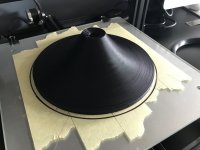
A cone mold after being printed, about an 8 hour job:
http://kensonger.com/field_coil/diyaudio/cone_mold_printed.jpeg
The printed molds are primed and sanded a few times, and then finally sealed with an acrylic cold glaze. A full set of cones drying, with a voice coil sitting on top of one of them:
http://kensonger.com/field_coil/diyaudio/cones_drying.jpeg
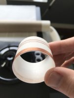
A trimmed voice coil, fresh off the winding assembly:
http://kensonger.com/field_coil/diyaudio/voice_coil.jpeg
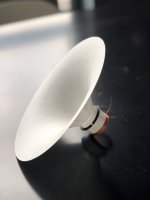
A cone and voice coil assembled and ready to be centered and attached to the spider assembly:
http://kensonger.com/field_coil/diyaudio/cone_and_coil.jpeg
Water saturated leather surrounds, ready to sit in front of the fireplace and dry out. The outer excess isn't trimmed away until it's been attached to the finished cone and glued down to the basket rim:
http://kensonger.com/field_coil/diyaudio/wet_surrounds.jpeg
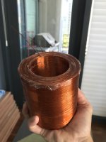
A solenoid right after coming off the bobbin. Next, extra epoxy is trimmed away and the coil is wrapped with a durable gaffers tape:
http://kensonger.com/field_coil/diyaudio/solenoid.jpeg
Cheers,
Ken
I thought people may want to see some images of the individual elements of the driver and the making of them in progress.
A cone mold after being printed, about an 8 hour job:
http://kensonger.com/field_coil/diyaudio/cone_mold_printed.jpeg
The printed molds are primed and sanded a few times, and then finally sealed with an acrylic cold glaze. A full set of cones drying, with a voice coil sitting on top of one of them:
http://kensonger.com/field_coil/diyaudio/cones_drying.jpeg
A trimmed voice coil, fresh off the winding assembly:
http://kensonger.com/field_coil/diyaudio/voice_coil.jpeg
A cone and voice coil assembled and ready to be centered and attached to the spider assembly:
http://kensonger.com/field_coil/diyaudio/cone_and_coil.jpeg
Water saturated leather surrounds, ready to sit in front of the fireplace and dry out. The outer excess isn't trimmed away until it's been attached to the finished cone and glued down to the basket rim:
http://kensonger.com/field_coil/diyaudio/wet_surrounds.jpeg
A solenoid right after coming off the bobbin. Next, extra epoxy is trimmed away and the coil is wrapped with a durable gaffers tape:
http://kensonger.com/field_coil/diyaudio/solenoid.jpeg
Cheers,
Ken
Attachments
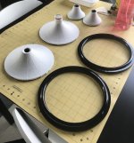
Thank you for posting more details. I presume the rings in the second picture are molds for shaping the leather surrounds? also 32 printed, primed and smoothed presumably?
Hey pcgab - my pleasure. Yep, the two sections are printed separately and finished in the same way. The cone and surround molds fit together for each pair. It's surprising how accurate the prints are - they essentially slip fit right off the bed. You see them together in the picture of the soaked leather surrounds.Thank you for posting more details. I presume the rings in the second picture are molds for shaping the leather surrounds? also 32 printed, primed and smoothed presumably?
Wow very very nice work. Btw I've always wondered how much cone profiles would affect the sound, have you experimented with profiles ?
Thks
Thks
Thanks so much for the wonderful compliments, all! Vitorio, I love Spain - my wife and I hope to move there some day. Have you heard Alsyvox? Such wonderful loudspeakers... Sorry for the short little installment here, but I ran out of time today and wanted to to post something nonetheless. Tomorrow, I'll have something more detailed and informative, particularly around testing methods and results, and the cabinets. Hope everyone enjoys the pics. 🙂
I thought people may want to see some images of the individual elements of the driver and the making of them in progress.
A solenoid right after coming off the bobbin. Next, extra epoxy is trimmed away and the coil is wrapped with a durable gaffers tape:
http://kensonger.com/field_coil/diyaudio/solenoid.jpeg
Cheers,
Ken
Wow, great photos to illustrate your process. Keep it up! LOVE that field coil! That's a big hunk of copper. I'm new to field coil speakers and never really thought about what they would need.
- Home
- Loudspeakers
- Full Range
- Creating a Field Coil Driver & Loudspeaker