Hey sumotan! I've experimented very little with different cone shapes, although I have read on the topic.
The whizzer cone in the final driver is quite a bit larger than what was used in the first 'proof-of-concept' driver. It made sense to me that a very stiff and light whizzer can benefit from increased size, because it stands a better chance of meeting the main cone... In other words, I wanted to be sure that the whizzer produced frequencies low enough to meet or overlap with the highest usable frequency cutoff of the main cone.
Some general ideas are that a deeper cone is better for low frequencies, a shallow cone is better for high frequencies, and a curvilinear cone does the better job of covering a broad frequency range and is radially stiffer than a straight cone.
While I can't seem to relocate the reference on the web that suggested it, I've also read that the location of the apex on the curve profile of the cone will affect the vibration of the cone at the apex, and reinforce a frequency range. I'm not entirely sure if that's true, but it seems plausible that it is.
When creating the conic curve profiles for the cones, a rho value of 0.5 always looked ideal to my eye. So... that means to me (for better or worse) a parabolic curve looks like the perfect cone profile shape.
Hey pcgab - I will one day circle back to the glass cabinets, although with a better design. Since I've got a CNC router always available now, I can put it to work cutting out intricate designs through the mahogany panels. I'll then line the entire inside of the box with inset 1/4" glass. With a flexible adhesive layer binding the wood and glass, the cabinet should be about as free of unwanted resonance as I can hope for.
Carl - yes, my wrists can attest to how serious field coils are to wind by hand. Should you attempt the feat, book your cortisone shots in advance.")
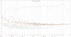
Picking up where I left off... the SPL/FR measurement was both good and bad.
After sharing the measurements with others (thank you, Mattes and Chris), I learned that I had a port/cabinet resonance problem at about 150Hz. The length of a 150Hz sound wave is 90 inches, and the internal height of the cabinet is 45 inches (1/2 of the wavelength) which means that stuffing the middle of the cabinet (1/4 of the wavelength) just until the resonance no longer appeared in the graph may work to correct the problem, albeit at the expense of some precious bass output.
This is an old measurement pulled from a prototype driver version, but taking a 1 meter full range measurement (in black) and overlaying it with a nearfield measurement at the port mouth (in red) shows that the problem also was at or near the fundamental output of the port.
http://www.kensonger.com/field_coil/br1/left_nearfield_plus_port.png
So, another option to correct the problem may have been to move the port location.
A third option is an Internal Helmholtz Resonator. That can be either a ported box internal to the speaker cabinet that is tuned to the standing resonance frequency, or it can be a barrier layer median to the inside of the cabinet with a series of holes of the right diameter drilled through it in a specific, calculated grid pattern.
The IHR will eventually be the gold standard solution in my loudspeakers, but for the short term I've found that minimal stuffing of the cabinet at the midpoint has resolved the problem admirably, even if I did expend 2dB of SPL below 100Hz in trade. The difference in clarity and imaging has been a clinic in critical listening. It's so much easier to identify the artificial 'thickness' of cabinet/port resonances in a speaker after having first lived with it for months, and then suddenly having had it removed it from the presentation. I can see why some designers deliberately design for a resonance that they find desirable, too - that 'thickness', particularly in the vocal range, has a certain panache to it. I thought I'd likely be one of those 'panache' guys, subscribing to the idea that the speaker itself is the last instrument on stage... but, it turns out that I'm not after all.
What I still don't understand is how the trained eye initially identifies a cabinet resonance among room effects and other artifacts. For example, this is a measurement with the last prototype driver in cabinet that shows the 150Hz resonance:
http://www.kensonger.com/field_coil/br1/left_frequency_impulse_response.png
If anyone would like to offer insight on the topic, I'd love to learn more.
Regarding measuring speakers generally I've come a long way. REW is more consistent and fully featured than the software side of Dayton OmniMic - I'd recommend it. It suffers from the reputation of having a steep learning curve, but that hasn't been my experience. It recognized my OmniMic microphone the first time it was launched, taking measurements has been intuitive, and results are repeatable and trustworthy.
Someday soon I need to take free-air measurements elevated from the ground to get the most accurate 500Hz - 20,000Hz readings (short of a professional anechoic chamber, that is). But for now I've been taking several on and off axis readings indoors with a few feet of space around the speaker and 7 feet away, along with a nearfield reading as close to the cone as possible for the 20-500Hz range. Those are first spatially and then vector averaged in REW to produce a single representative response of a 30° listening window in the room.
Allow me to re-gift a couple of nice references shared with me a couple of months ago on how to take good measurements:
The Danger Zone.pdf - Google Drive
HiFi Loudspeaker Design
Alright... that's it for today! Hope the reading continues to offer value, cheers all.
- Ken
The whizzer cone in the final driver is quite a bit larger than what was used in the first 'proof-of-concept' driver. It made sense to me that a very stiff and light whizzer can benefit from increased size, because it stands a better chance of meeting the main cone... In other words, I wanted to be sure that the whizzer produced frequencies low enough to meet or overlap with the highest usable frequency cutoff of the main cone.
Some general ideas are that a deeper cone is better for low frequencies, a shallow cone is better for high frequencies, and a curvilinear cone does the better job of covering a broad frequency range and is radially stiffer than a straight cone.
While I can't seem to relocate the reference on the web that suggested it, I've also read that the location of the apex on the curve profile of the cone will affect the vibration of the cone at the apex, and reinforce a frequency range. I'm not entirely sure if that's true, but it seems plausible that it is.
When creating the conic curve profiles for the cones, a rho value of 0.5 always looked ideal to my eye. So... that means to me (for better or worse) a parabolic curve looks like the perfect cone profile shape.
Hey pcgab - I will one day circle back to the glass cabinets, although with a better design. Since I've got a CNC router always available now, I can put it to work cutting out intricate designs through the mahogany panels. I'll then line the entire inside of the box with inset 1/4" glass. With a flexible adhesive layer binding the wood and glass, the cabinet should be about as free of unwanted resonance as I can hope for.
Carl - yes, my wrists can attest to how serious field coils are to wind by hand. Should you attempt the feat, book your cortisone shots in advance.
Picking up where I left off... the SPL/FR measurement was both good and bad.
After sharing the measurements with others (thank you, Mattes and Chris), I learned that I had a port/cabinet resonance problem at about 150Hz. The length of a 150Hz sound wave is 90 inches, and the internal height of the cabinet is 45 inches (1/2 of the wavelength) which means that stuffing the middle of the cabinet (1/4 of the wavelength) just until the resonance no longer appeared in the graph may work to correct the problem, albeit at the expense of some precious bass output.
This is an old measurement pulled from a prototype driver version, but taking a 1 meter full range measurement (in black) and overlaying it with a nearfield measurement at the port mouth (in red) shows that the problem also was at or near the fundamental output of the port.
http://www.kensonger.com/field_coil/br1/left_nearfield_plus_port.png
So, another option to correct the problem may have been to move the port location.
A third option is an Internal Helmholtz Resonator. That can be either a ported box internal to the speaker cabinet that is tuned to the standing resonance frequency, or it can be a barrier layer median to the inside of the cabinet with a series of holes of the right diameter drilled through it in a specific, calculated grid pattern.
The IHR will eventually be the gold standard solution in my loudspeakers, but for the short term I've found that minimal stuffing of the cabinet at the midpoint has resolved the problem admirably, even if I did expend 2dB of SPL below 100Hz in trade. The difference in clarity and imaging has been a clinic in critical listening. It's so much easier to identify the artificial 'thickness' of cabinet/port resonances in a speaker after having first lived with it for months, and then suddenly having had it removed it from the presentation. I can see why some designers deliberately design for a resonance that they find desirable, too - that 'thickness', particularly in the vocal range, has a certain panache to it. I thought I'd likely be one of those 'panache' guys, subscribing to the idea that the speaker itself is the last instrument on stage... but, it turns out that I'm not after all.
What I still don't understand is how the trained eye initially identifies a cabinet resonance among room effects and other artifacts. For example, this is a measurement with the last prototype driver in cabinet that shows the 150Hz resonance:
http://www.kensonger.com/field_coil/br1/left_frequency_impulse_response.png
If anyone would like to offer insight on the topic, I'd love to learn more.
Regarding measuring speakers generally I've come a long way. REW is more consistent and fully featured than the software side of Dayton OmniMic - I'd recommend it. It suffers from the reputation of having a steep learning curve, but that hasn't been my experience. It recognized my OmniMic microphone the first time it was launched, taking measurements has been intuitive, and results are repeatable and trustworthy.
Someday soon I need to take free-air measurements elevated from the ground to get the most accurate 500Hz - 20,000Hz readings (short of a professional anechoic chamber, that is). But for now I've been taking several on and off axis readings indoors with a few feet of space around the speaker and 7 feet away, along with a nearfield reading as close to the cone as possible for the 20-500Hz range. Those are first spatially and then vector averaged in REW to produce a single representative response of a 30° listening window in the room.
Allow me to re-gift a couple of nice references shared with me a couple of months ago on how to take good measurements:
The Danger Zone.pdf - Google Drive
HiFi Loudspeaker Design
Alright... that's it for today! Hope the reading continues to offer value, cheers all.
- Ken
Last edited:
Are you all electrostatic now?
No. They generally make speakers with permanent magnets these days.
Last edited:
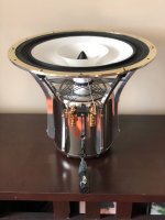
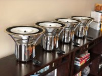
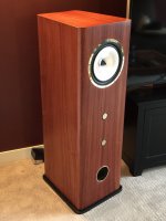
For those of you who didn't find this thread via the full range photo gallery, here are the images I shared there (attached below), of the finished 'production' driver and loudspeaker versions, and how the speaker measured in the end.
Picking up where the last post left off, measurements are not everything.
A line on a graph just can't capture everything there is about a great listening experience. That leads me to my next topic, which is the spider assembly I eventually registered a patent for (which feels indulgent to say, of course).
The typical spider design only made sense to me for it's reliability and durability - the solution is if nothing else time tested. On the other hand, stiff resin soaked cloth hanging as dead weight from the former seemed an unfortunate need at best, and a real restriction at worst. Any sort of dead weight on the moving mass seems like a misfortune for an agile, full range driver.
I imagined that a very wide, thin 'matrix' of material with just the right elasticity anchored to the former and frame held in subtle even tension may meet my initial design goals. A wide footprint (perhaps the diameter of the main cone) should be unusually compliant... and, if the material wasn't excessively elastic it should be equally stable in centering the former in the gap.
The first effort followed a forum post speculation, and was silk - but as mentioned earlier it wasn't durable enough. I turned to 3D printing next, looking for something more effective. After trying out half a dozen samples from different companies, I chose a thermal polyurethane with a medium-low elasticity. Recommended to produce gaskets for engines, it was going to be more than durable enough for this use. Over a long period of time I tried many versions, eventually settling on a pattern of 30 intersecting strands connected to the frame arms and former.
To work, the attachment method of spider to former needed re-thinking too. It'd be all but impossible to perfectly attach, level and center the former using nothing but the flexible matrix. Again, there were many prototypes along the way but the most successful was a two part solution connecting a hard, composite collar at the matrix center to an extremely light and thin 'shelf' of the same material affixed to the former in sections. A benefit of the very rigid composite shelf is that it likewise prevents former deformation, likely even under the worst of conditions.
Assembly is effortless; after the spider is attached to the frame, the entire remaining moving mass can be shimmed for centering, eased onto it, and left to cure. Lastly, the leather is glued down to the rim, and excess trimmed the next day. Perfect results, every time.
When I conversationally showed exhibitors pictures the driver at the 2018 Capital AudioFest later that year, one was particularly interested in it (a wonderful, generous spirited guy) - as a driver option in his own line of products. The spider was less substantial a matrix at the time, and his only open concern with my driver was it's durability... or rather, the spider's lacking appearance of durability to his customers.
I was excited, and very interested in the opportunity for a partnership together. So I went home and spent two months tirelessly prototyping around factory spiders. I bought the lightest, most compliant versions that I could find anywhere, and when even those seemed not compliant enough I modified them further for greater softness. I modified the frame to accommodate them, and designed and printed fixtures to hold them in place.
And now, I'm finally arriving at my point (thank god for that, eh?). The two driver versions with either custom or factory spiders measured virtually identically. Without them labelled, even I couldn't often tell the graphs apart.
But they did not sound the same, no... not at all. The factory spider version, in spite of having measured very slightly better in treble performance, sounded utterly lifeless. The intricate, inner detail of recordings was muted, disengaging and all but lost. The image was unconvincing, and without depth or focus. Percussion had no infectious cadence. In fact, it was SO much worse than the custom spider had been that after the first listening session, I sulked slowly out of the room and declared to my wife that I didn't want to do this speaker stuff anymore. I was done... tired and defeated.
I picked myself up after a few days. And when I did, I redesigned the custom spider to it's current version, with slightly softer compliance and more than double the matrix strands of the one I'd shown around in DC. In fact, the custom version sounded even better now than it had before the months of experimenting.
I learned a few great lessons. First, even the most benevolent, sage and considered advice may occasionally miss the mark, or may be brilliant for some circumstances but simply not aligned with yours. Second, as previously said, there is absolutely no substitute for the experience of sitting in front of a speaker and listening to it... how it sounds and makes you feel. Certainly (important as it is) not with reading how it measures.
Lastly, I learned that it's unquestionably the spider that makes this driver so special. That was reinforced in me last November when the CEO of a German studio monitor company looked at the spider at a local industry event and advised me that I shouldn't show it in public again until taking out a patent on it. He felt that I may see more success in promoting and licensing it's design than I could making drivers or speakers. I still think that's just silly.
But you know... not so silly that I didn't pay for the patent.
Cheers, all.
Attachments
Last edited:
You missed the point... Electrodynamic speaker driver - WikipediaNo. They generally make speakers with permanent magnets these days.
@pcgab - I took a pass through the archives this morning to be sure, and unfortunately the only surviving record of that dark episode are a few Omnimic FR measurements. But I've thought the same thing since then - IR might have told some or all of the tale. I was so disappointed at the time that I couldn't bear to perform the proper autopsy... now of course I wish I had. I may have come away with a better understanding of the factors that eventually predicted success.
@454Casull - Yes, if the motor weight was suspended by the basket it would surely distort, if only a little bit.
When I imagined the mechanics of it years ago, a meaningfully load-bearing basket was ruled out early on. Suspending 35lbs horizontally from a frame that didn't itself weigh 15-20 lbs in the hope that it wouldn't some day misalign by 0.2mm seemed... implausible. Having made early prototypes with misaligned geometry, the thought of selling a driver that eventually experienced voice coil rubbing kept me awake nights... visions of a boxed up pair of the speakers bouncing wildly around in the back of a tractor trailer across a thousand miles of poorly maintained freeways, ugh.
So... I started to think about the function of the basket differently. The basket and flange bear the shared duty of preventing forward and backward motion against the baffle with six M4 bolts. The rest of the responsibility is taken by an M10 bolt mounting point below the driver terminals. In the finished loudspeaker, that carbon steel bolt runs through an arch inside the cabinet and through the motor housing - I'll include pictures of that soon, when posting about the cabinet construction. I haven't tried it - but I'm pretty confident that with the cabinet in a partially assembled state, I could stand on the mounted motor and the voice coil wouldn't rub one bit. Even that may not prevent me from adding a small degree of further substance to the frame arms should I be fortunate enough to sell my work. As previously mentioned... if I want peace of mind, then I'll do well not to make guesses.
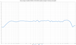
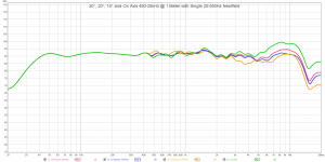
Thank you adason! Sure thing, the graph is attached below for those measurements. They share a common nearfield 20-550Hz range, and the on and off axis measurements were taken at 1 meter and cover 450-20,000Hz. If you'd like to see something a little different, please feel free to ask. I'll take free-field measurements one of these days soon.
@454Casull - Yes, if the motor weight was suspended by the basket it would surely distort, if only a little bit.
When I imagined the mechanics of it years ago, a meaningfully load-bearing basket was ruled out early on. Suspending 35lbs horizontally from a frame that didn't itself weigh 15-20 lbs in the hope that it wouldn't some day misalign by 0.2mm seemed... implausible. Having made early prototypes with misaligned geometry, the thought of selling a driver that eventually experienced voice coil rubbing kept me awake nights... visions of a boxed up pair of the speakers bouncing wildly around in the back of a tractor trailer across a thousand miles of poorly maintained freeways, ugh.
So... I started to think about the function of the basket differently. The basket and flange bear the shared duty of preventing forward and backward motion against the baffle with six M4 bolts. The rest of the responsibility is taken by an M10 bolt mounting point below the driver terminals. In the finished loudspeaker, that carbon steel bolt runs through an arch inside the cabinet and through the motor housing - I'll include pictures of that soon, when posting about the cabinet construction. I haven't tried it - but I'm pretty confident that with the cabinet in a partially assembled state, I could stand on the mounted motor and the voice coil wouldn't rub one bit. Even that may not prevent me from adding a small degree of further substance to the frame arms should I be fortunate enough to sell my work. As previously mentioned... if I want peace of mind, then I'll do well not to make guesses.
Thank you adason! Sure thing, the graph is attached below for those measurements. They share a common nearfield 20-550Hz range, and the on and off axis measurements were taken at 1 meter and cover 450-20,000Hz. If you'd like to see something a little different, please feel free to ask. I'll take free-field measurements one of these days soon.
Attachments
Last edited:
Thanks @adason, that's good to hear. I wonder if the curvilinear main and whizzer cones offer better off-axis results? Comments welcome, if someone has a thought on that.
Okay... on to cabinets and circuits. When first modeling response for the driver/cabinet in WinSpeakerz, the software suggested a variety of ported enclosures of about 2.5 cubic feet (70 liters) with a -3dB drop-off at about 50Hz. The bass response wasn't as good as I'd hoped for from a 10" driver... so, I began to experiment with both cabinet and driver values to get a sense of what predicted better bass extension.
Of course, on the cabinet side of the equation volume and port tuning predicted outcome. How big to go, then..? Modeling some basic tapered box shapes in Fusion 360 allowed me to visualize what sizes might actually look like. 140 liters still narrowly avoided absurdity, and offered much greater bass potential. Regarding port tuning, tuning too low for any given volume caused an excessive roll-off in bass, while too high produced a big peak above the baseline response.
On the driver side of the equation, two T/S parameters strongly correlated with better bass performance: lowering Fs and raising Qts. I couldn't realistically lower the driver Fs - it was already 19Hz - so that left me with trying to raise Qts.
There are a few ways to do that. One is to add more mass to the cone(s), a proposal squarely at odds with my initial design principles. Another is to increase the windings of the voice coil, which likewise adversely affects both mass and the travel of the underhung coil in the gap. A third option (which seemed too good to be true) is to simply add a passive resistor in series with the driver. Doing so increases Qes and subsequently the total Q. If it worked well, that route was going to be an obvious choice for me. While the series resistor reduces driver sensitivity and is admittedly wasteful, it seemed wise to trade some of a resource I had in ample abundance in exchange for another I had very little of.
One last issue remained open in my mind... whether or not to add a shorting ring to the final driver for improved treble extension and lower distortion. I didn't address it at the time, but I'll revisit that topic a little later.
I had a good initial plan, then. I'd build a 140 liter cabinet, then fine tune the response measurements with a combination of a series resistor and a BSC circuit to balance out the response.
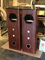
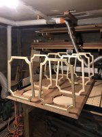
An off-topic, but worthwhile note: when I began this odyssey years ago I'd had a large community maker-space to work from (which I'd recommend to anyone with a passion for this but no workspace, btw), complete with well-appointed CAD, metal, textile and wood shops, and a 4'x8' CNC router. The 'production prototypes' of the cabinet described above were made there, however last fall the shop went out of business, and I was left to find a new place to work.
My best pal (being the splendid bastard that he is) offered me use of his small garage, and together we outfitted it with some basic equipment and a small but quite capable CNC router of our own. The images to follow are taken from that period, rather than the old maker-space. A tiny garage is untenable in the long term, but my wife and I have found a 'dream home' just recently that we may put in an offer for after this pandemic passes by. It's a large mixed use property, with 1100 square feet of ideal commercial space on the street level... the new and final home of my endeavors, should it all work out. Fingers crossed.
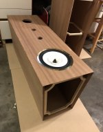
After routing out each cabinet panel and miter cutting the joining edges on the table saw, these were the baffles with a first set of braces glued up to them:
http://kensonger.com/field_coil/cabinet_braces.jpg
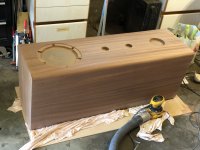
The finished cabinet likewise includes thick braces running lengthwise down each of the four corners, and an arch-shaped brace at driver level that supports the motor.
The placement of the arch braces must be precise if they are to support the motor well. That necessitates temporarily mounting a driver on baffle, aligning the motor-facing surface of the arch to the arch-facing motor exterior, and then with glue applied to the ends of the arch, pushing it steadily toward the rear of the cabinet such that as the width of the cabinet interior narrows, the arch becomes tensioned very, very tightly in place.
http://kensonger.com/field_coil/placing_arches.jpg
http://kensonger.com/field_coil/arches_installed.jpg
This is an example of where modeling everything first in a digital space really shines. After gluing the arches in place, it's wonderful to confirm that the motor mounting hole in the middle of the arch aligns flawlessly with the corresponding M10 mounting point on the motor housing. That'd be a difficult feat, at best, without 3D modeling and CNC routing.
For both aesthetic reasons and to reduce baffle edge effects, the cabinet was manually routed with a 1" round-over bit, set about 3mm deeper than the baffle face and then blended into the flat face of the baffle for a gradual curve. The entire cabinet was then sanded to a 400 grit surface.
http://kensonger.com/field_coil/routed_and_sanded.jpg
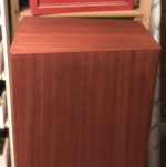
The first finishing step is staining. For these cabinets I wanted a rich, warm mahogany color. The final shade that looked best to me was a diluted blend of vintage cherry and empire red dye stain from General Finishes:
http://kensonger.com/field_coil/stain.jpg
Sapele mahogany is an open-grained wood with fairly large pores. For woods like this, the next finishing step is to grain fill it. I chose a crystal clear, non-toxic water-based product that wouldn't interfere with the natural appearance of the wood itself. Once dry, it's sanded gently back just to the exposed wood, being careful to leave the filler in the pores and not sand through into the stain.
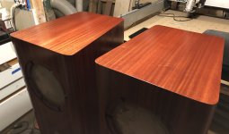
The next step is three coats of shellac, to seal the stained wood and impart depth to the grain and a nice golden hue. The beautiful chatoyance in the mahogany really starts to show (you get a sense of it in the front corner of the furthest cabinet):
http://kensonger.com/field_coil/shellac_applied_tops.jpg
For a durable top coat, lacquer is my favorite choice. I apply six coats of Deft, and after curing for a couple of days it's ready to be rubbed to a final satin gloss. That's done with a piece 0000 steel wool, saturated with Murphy's Oil Soap. Pictured below after that step, the bases are sitting on top of the cabinets, and the unpolished brass accompaniments dropped in place just to see how it's all shaping up so far:
http://kensonger.com/field_coil/ready_for_brass.jpg
As you'd imagine... by the time these were complete (particularly, made in such humble accommodations) I couldn't wait to listen to them. And, to turn my attention back to the less physically taxing matter of taking the final steps to perfect the speaker response.
That's all the time I've got for today. I'll try to add the next chapter in the story tomorrow... stay healthy and sane everyone.
Okay... on to cabinets and circuits. When first modeling response for the driver/cabinet in WinSpeakerz, the software suggested a variety of ported enclosures of about 2.5 cubic feet (70 liters) with a -3dB drop-off at about 50Hz. The bass response wasn't as good as I'd hoped for from a 10" driver... so, I began to experiment with both cabinet and driver values to get a sense of what predicted better bass extension.
Of course, on the cabinet side of the equation volume and port tuning predicted outcome. How big to go, then..? Modeling some basic tapered box shapes in Fusion 360 allowed me to visualize what sizes might actually look like. 140 liters still narrowly avoided absurdity, and offered much greater bass potential. Regarding port tuning, tuning too low for any given volume caused an excessive roll-off in bass, while too high produced a big peak above the baseline response.
On the driver side of the equation, two T/S parameters strongly correlated with better bass performance: lowering Fs and raising Qts. I couldn't realistically lower the driver Fs - it was already 19Hz - so that left me with trying to raise Qts.
There are a few ways to do that. One is to add more mass to the cone(s), a proposal squarely at odds with my initial design principles. Another is to increase the windings of the voice coil, which likewise adversely affects both mass and the travel of the underhung coil in the gap. A third option (which seemed too good to be true) is to simply add a passive resistor in series with the driver. Doing so increases Qes and subsequently the total Q. If it worked well, that route was going to be an obvious choice for me. While the series resistor reduces driver sensitivity and is admittedly wasteful, it seemed wise to trade some of a resource I had in ample abundance in exchange for another I had very little of.
One last issue remained open in my mind... whether or not to add a shorting ring to the final driver for improved treble extension and lower distortion. I didn't address it at the time, but I'll revisit that topic a little later.
I had a good initial plan, then. I'd build a 140 liter cabinet, then fine tune the response measurements with a combination of a series resistor and a BSC circuit to balance out the response.
An off-topic, but worthwhile note: when I began this odyssey years ago I'd had a large community maker-space to work from (which I'd recommend to anyone with a passion for this but no workspace, btw), complete with well-appointed CAD, metal, textile and wood shops, and a 4'x8' CNC router. The 'production prototypes' of the cabinet described above were made there, however last fall the shop went out of business, and I was left to find a new place to work.
My best pal (being the splendid bastard that he is) offered me use of his small garage, and together we outfitted it with some basic equipment and a small but quite capable CNC router of our own. The images to follow are taken from that period, rather than the old maker-space. A tiny garage is untenable in the long term, but my wife and I have found a 'dream home' just recently that we may put in an offer for after this pandemic passes by. It's a large mixed use property, with 1100 square feet of ideal commercial space on the street level... the new and final home of my endeavors, should it all work out. Fingers crossed.
After routing out each cabinet panel and miter cutting the joining edges on the table saw, these were the baffles with a first set of braces glued up to them:
http://kensonger.com/field_coil/cabinet_braces.jpg
The finished cabinet likewise includes thick braces running lengthwise down each of the four corners, and an arch-shaped brace at driver level that supports the motor.
The placement of the arch braces must be precise if they are to support the motor well. That necessitates temporarily mounting a driver on baffle, aligning the motor-facing surface of the arch to the arch-facing motor exterior, and then with glue applied to the ends of the arch, pushing it steadily toward the rear of the cabinet such that as the width of the cabinet interior narrows, the arch becomes tensioned very, very tightly in place.
http://kensonger.com/field_coil/placing_arches.jpg
http://kensonger.com/field_coil/arches_installed.jpg
This is an example of where modeling everything first in a digital space really shines. After gluing the arches in place, it's wonderful to confirm that the motor mounting hole in the middle of the arch aligns flawlessly with the corresponding M10 mounting point on the motor housing. That'd be a difficult feat, at best, without 3D modeling and CNC routing.
For both aesthetic reasons and to reduce baffle edge effects, the cabinet was manually routed with a 1" round-over bit, set about 3mm deeper than the baffle face and then blended into the flat face of the baffle for a gradual curve. The entire cabinet was then sanded to a 400 grit surface.
http://kensonger.com/field_coil/routed_and_sanded.jpg
The first finishing step is staining. For these cabinets I wanted a rich, warm mahogany color. The final shade that looked best to me was a diluted blend of vintage cherry and empire red dye stain from General Finishes:
http://kensonger.com/field_coil/stain.jpg
Sapele mahogany is an open-grained wood with fairly large pores. For woods like this, the next finishing step is to grain fill it. I chose a crystal clear, non-toxic water-based product that wouldn't interfere with the natural appearance of the wood itself. Once dry, it's sanded gently back just to the exposed wood, being careful to leave the filler in the pores and not sand through into the stain.
The next step is three coats of shellac, to seal the stained wood and impart depth to the grain and a nice golden hue. The beautiful chatoyance in the mahogany really starts to show (you get a sense of it in the front corner of the furthest cabinet):
http://kensonger.com/field_coil/shellac_applied_tops.jpg
For a durable top coat, lacquer is my favorite choice. I apply six coats of Deft, and after curing for a couple of days it's ready to be rubbed to a final satin gloss. That's done with a piece 0000 steel wool, saturated with Murphy's Oil Soap. Pictured below after that step, the bases are sitting on top of the cabinets, and the unpolished brass accompaniments dropped in place just to see how it's all shaping up so far:
http://kensonger.com/field_coil/ready_for_brass.jpg
As you'd imagine... by the time these were complete (particularly, made in such humble accommodations) I couldn't wait to listen to them. And, to turn my attention back to the less physically taxing matter of taking the final steps to perfect the speaker response.
That's all the time I've got for today. I'll try to add the next chapter in the story tomorrow... stay healthy and sane everyone.
Attachments
Mind-boggling work for an individual. I would love to hear some more tests plays. /me stares longingly at the Atwater Kent motor gathering dust in the corner...
Have to agree with that. Mindboggling to be sure. Congratulations gomper!
Thanks again everyone, for the kind words; they're especially appreciated as I'm waiting for the covid-19 era to end. It's ironic to have completed this five year journey just in time to be unable to share it with anyone in person.
So @Godataloss... while I can't share in person, and I don't have the means to record something professional, I'm going to shoot for next best in this post by sharing some recordings made yesterday afternoon. They were captured with my iPhone and an OmniMic running through Audacity.
For your maximum listening pleasure I recommend headphones, or anything else that offers decent bass response. Hopefully somehow, perhaps by way of rich imagination, these amateur videos confer a small glimpse of how wonderful they sound in person.
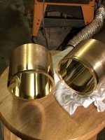
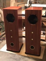
Returning to the speakers themselves, the last thing to be done with the cabinets was to polish up and install all of the brass elements, attach the bases and drop in a pair of drivers.
The ports looked like this, after hand polishing the exposed faces and shortly before being installed on the baffles:
http://kensonger.com/field_coil/polished_ports.jpg
The finished cabinets awaiting a pair of drivers looked like this:
http://kensonger.com/field_coil/ready_for_drivers.jpg
The only further details to offer are regarding the interior treatment. All of the inside panel surfaces have a 1/2 inch thick sonic barrier applied, save the section just behind the port, which is left to exposed wood. The middle section between the second and third braces includes two layers of Bonded Logic UltraTouch to reduce cabinet resonance, firmly tied back via the brace corner sections and leaving about a 4x6" opening of free air in the interior between the driver and port. The arch was eventually painted with black latex, and wrapped with sonic barrier to further reduce any reflections back through the cone, and a lightweight, black speaker cloth panel added a few inches away from the inside end of the port, for purely aesthetic purposes.
Around the time that last picture was taken, I circled back to the prototype drivers to decide on shorting rings. A shorting ring for those of you who haven't heard of them, is typically a single shorted turn of copper or other conductive metal. It's either a thin sleeve in the magnetic gap, or a somewhat thick ring just above or below it. The effects of the ring are to flatten out rising impedance in the upper frequency range, which improves treble performance, and to reduces voice coil inductance modulation, which in turn reduces distortion.
I went with a thick shorting ring below the gap, attached to the pole piece. Measured in DATS however, I didn't see any effect on the impedance curve. I can't explain that, unfortunately... theories are welcome. In cabinet on the other hand, the effect on the sound was easy to hear. The image was sharper, and detail retrieval was simply amazing. It was definitely a little too bright, too, but a brighter presentation may just change where and how much attenuation was needed for the BSC circuit.
Confident of the improvement, I added shorting rings to all of the production drivers as well, and... they didn't sound good at all. The first listen was in the final cabinets above, in a spacious room with reasonably good acoustics. Where the prototype driver pair had sounded a little too bright, the production drivers were searingly bright. They were too bright to listen to for more than 30 minutes or so before experiencing ear fatigue - none of the past versions has ever caused that. I spent quite a few days thinking it over, trying to figure out why two drivers that seemed so identical could sound so different with the same modification.
The only difference I could think of was the surface treatment on the motors. The prototype driver motor was just polished, bare carbon steel. But steel even under the best of circumstances will eventually rust; so, for the production drivers I had a fairly thick bright nickel plating applied to them inside and out. The only part of the motor assembly free of the nickel plating was the gap.
Nickel is not as conductive as copper or aluminum of course... but it certainly does conduct. And with that in mind I started to think back upon a comment I read some months prior from the esteemed driver maker Haruhiko Teramoto, which at the time I must confess I dismissed as a bit ridiculous. In discussing the surface treatment on his latest drivers, he claimed that different finishes on the steel altered the way the driver ended up sounding. He ended up choosing a special kind of lacquer.
Maybe he was right after all... and in any case what he said has provided me with a theory. The nickel plating covers the entire motor and when I think about it's geometry on the surface... it's actually a big, shorted ring of conductive metal. It gets better: there are two of them. One of them is of course on the exterior of the motor, with it's effective inner diameter being the gap, which has no plating. The other is on the inside surface, likewise covering the entire surface of the steel and terminating at the gap. And that, as crazy as it may sound, is why I think the production drivers are both brighter and more detailed than the prototypes are. They already have shorting rings of a sort, both above and below the gap.
The last variable that I can see in my experience with and without shorting rings is the manner of amplification - I'm using a tube amp. These speakers really shine with tube amplification, and that makes a good deal of sense for a highly self-damping field coil driver. But also of importance, tube amplification power is directly proportional to speaker impedance. Conversely, in a solid state amplifier power delivery is inversely proportional to speaker impedance, and therefore power decreases as the speaker impedance rises. With that in mind, it seems plausible that drivers with shorting rings make the best sense for solid state amplification (and, may not at all for tube amplification) because they improve what would otherwise be falling treble performance as impedance rises and solid state power decreases right along with it. I'd venture further to guess that for optimal all-around performance in a solid state system, a multi-way speaker further improves design opportunities for tailoring a balanced response. If all of that is generally accurate, then it likewise could follow that in the case of a point source full-range field coil loudspeaker, tube amplification isn't optional... it's all but a necessity.
Okay, here are those test plays, as promised. I was a little worried about hosting them on my own site, just in case they receive a lot of traffic and it incurs bandwidth usage charges, so I made a nice little youtube channel for them:
"Home", by Dominique Fils-Aimé
YouTube
"Tin Pan Alley", by Stevie Ray Vaughan & Double Trouble
YouTube
"Heart's On Fire", by Passenger
YouTube
"No Sanctuary Here", by Chris Jones
https://youtu.be/sScAY6xiLfE
"Shenandoah", by Youn Sun Nah
https://youtu.be/MxLPagX04_A
"Electrified II", by Yello
https://youtu.be/3mE6B409vOg
Until next time, cheers. Hope you all enjoy.
So @Godataloss... while I can't share in person, and I don't have the means to record something professional, I'm going to shoot for next best in this post by sharing some recordings made yesterday afternoon. They were captured with my iPhone and an OmniMic running through Audacity.
For your maximum listening pleasure I recommend headphones, or anything else that offers decent bass response. Hopefully somehow, perhaps by way of rich imagination, these amateur videos confer a small glimpse of how wonderful they sound in person.
Returning to the speakers themselves, the last thing to be done with the cabinets was to polish up and install all of the brass elements, attach the bases and drop in a pair of drivers.
The ports looked like this, after hand polishing the exposed faces and shortly before being installed on the baffles:
http://kensonger.com/field_coil/polished_ports.jpg
The finished cabinets awaiting a pair of drivers looked like this:
http://kensonger.com/field_coil/ready_for_drivers.jpg
The only further details to offer are regarding the interior treatment. All of the inside panel surfaces have a 1/2 inch thick sonic barrier applied, save the section just behind the port, which is left to exposed wood. The middle section between the second and third braces includes two layers of Bonded Logic UltraTouch to reduce cabinet resonance, firmly tied back via the brace corner sections and leaving about a 4x6" opening of free air in the interior between the driver and port. The arch was eventually painted with black latex, and wrapped with sonic barrier to further reduce any reflections back through the cone, and a lightweight, black speaker cloth panel added a few inches away from the inside end of the port, for purely aesthetic purposes.
Around the time that last picture was taken, I circled back to the prototype drivers to decide on shorting rings. A shorting ring for those of you who haven't heard of them, is typically a single shorted turn of copper or other conductive metal. It's either a thin sleeve in the magnetic gap, or a somewhat thick ring just above or below it. The effects of the ring are to flatten out rising impedance in the upper frequency range, which improves treble performance, and to reduces voice coil inductance modulation, which in turn reduces distortion.
I went with a thick shorting ring below the gap, attached to the pole piece. Measured in DATS however, I didn't see any effect on the impedance curve. I can't explain that, unfortunately... theories are welcome. In cabinet on the other hand, the effect on the sound was easy to hear. The image was sharper, and detail retrieval was simply amazing. It was definitely a little too bright, too, but a brighter presentation may just change where and how much attenuation was needed for the BSC circuit.
Confident of the improvement, I added shorting rings to all of the production drivers as well, and... they didn't sound good at all. The first listen was in the final cabinets above, in a spacious room with reasonably good acoustics. Where the prototype driver pair had sounded a little too bright, the production drivers were searingly bright. They were too bright to listen to for more than 30 minutes or so before experiencing ear fatigue - none of the past versions has ever caused that. I spent quite a few days thinking it over, trying to figure out why two drivers that seemed so identical could sound so different with the same modification.
The only difference I could think of was the surface treatment on the motors. The prototype driver motor was just polished, bare carbon steel. But steel even under the best of circumstances will eventually rust; so, for the production drivers I had a fairly thick bright nickel plating applied to them inside and out. The only part of the motor assembly free of the nickel plating was the gap.
Nickel is not as conductive as copper or aluminum of course... but it certainly does conduct. And with that in mind I started to think back upon a comment I read some months prior from the esteemed driver maker Haruhiko Teramoto, which at the time I must confess I dismissed as a bit ridiculous. In discussing the surface treatment on his latest drivers, he claimed that different finishes on the steel altered the way the driver ended up sounding. He ended up choosing a special kind of lacquer.
Maybe he was right after all... and in any case what he said has provided me with a theory. The nickel plating covers the entire motor and when I think about it's geometry on the surface... it's actually a big, shorted ring of conductive metal. It gets better: there are two of them. One of them is of course on the exterior of the motor, with it's effective inner diameter being the gap, which has no plating. The other is on the inside surface, likewise covering the entire surface of the steel and terminating at the gap. And that, as crazy as it may sound, is why I think the production drivers are both brighter and more detailed than the prototypes are. They already have shorting rings of a sort, both above and below the gap.
The last variable that I can see in my experience with and without shorting rings is the manner of amplification - I'm using a tube amp. These speakers really shine with tube amplification, and that makes a good deal of sense for a highly self-damping field coil driver. But also of importance, tube amplification power is directly proportional to speaker impedance. Conversely, in a solid state amplifier power delivery is inversely proportional to speaker impedance, and therefore power decreases as the speaker impedance rises. With that in mind, it seems plausible that drivers with shorting rings make the best sense for solid state amplification (and, may not at all for tube amplification) because they improve what would otherwise be falling treble performance as impedance rises and solid state power decreases right along with it. I'd venture further to guess that for optimal all-around performance in a solid state system, a multi-way speaker further improves design opportunities for tailoring a balanced response. If all of that is generally accurate, then it likewise could follow that in the case of a point source full-range field coil loudspeaker, tube amplification isn't optional... it's all but a necessity.
Okay, here are those test plays, as promised. I was a little worried about hosting them on my own site, just in case they receive a lot of traffic and it incurs bandwidth usage charges, so I made a nice little youtube channel for them:
"Home", by Dominique Fils-Aimé
YouTube
"Tin Pan Alley", by Stevie Ray Vaughan & Double Trouble
YouTube
"Heart's On Fire", by Passenger
YouTube
"No Sanctuary Here", by Chris Jones
https://youtu.be/sScAY6xiLfE
"Shenandoah", by Youn Sun Nah
https://youtu.be/MxLPagX04_A
"Electrified II", by Yello
https://youtu.be/3mE6B409vOg
Until next time, cheers. Hope you all enjoy.
Attachments
Last edited:
Member
Joined 2009
Paid Member
simply amazing.
The very first thing I noticed was the spyder. Glad you patented it, it was literally the first thing I noticed and with the thought OMG, of course, that’s how it should be done!!
Well done indeed.
Thank you, Gareth! I've been a very busy guy this past week or so - but I'll be back with another post in the next few days. Cheers...
- Home
- Loudspeakers
- Full Range
- Creating a Field Coil Driver & Loudspeaker