Hey there!
I'm making plans to build my own open baffle full range speakers.
I have found scattered info about that, but I'm looking for a guide/book/article/ap with everything gathered. Like how to choose speakers, crossover, what wood, what dimensions etc...
Also is there any cad programm to do simulations and maybe a cad design of the final outcome?
Do you have any recommendations?
Thanks in advance for any help!
subscribed.
would be interested in H and U frame calculators also that are a bit quicker and easier to use than the MJK sheets (which have me stumped).
would be interested in H and U frame calculators also that are a bit quicker and easier to use than the MJK sheets (which have me stumped).
Single Driver Website
I downloaded and use:
Baffle spreadsheet calculator with room interaction - Excel - (Thorsten Loesch)
I find it helpful for getting the size of my baffles right before cutting any wood.
This is a pretty old spreadsheet. Maybe folks can begin enhancing it somehow?
I downloaded and use:
Baffle spreadsheet calculator with room interaction - Excel - (Thorsten Loesch)
I find it helpful for getting the size of my baffles right before cutting any wood.
This is a pretty old spreadsheet. Maybe folks can begin enhancing it somehow?
Whether or not you want to buy MJK's MathCAD worksheets (which I use & like very much), Martin's site has lots of good info on OB theory:
Quarter Wavelength Loudspeaker Design
Cheers, Jim
Quarter Wavelength Loudspeaker Design
Cheers, Jim
Open baffle speakers are too complex to simulate. You must iteratively build and measure. And you'd need decent reflection-free environment too, like outdoors.
simulators disregard that FR is different between front and back. And also ignore off axis situation. This leads to non-flat response and non-uniform dispersion.
SL have a great step by step process in designing OB speakers in linkwitzlab.
simulators disregard that FR is different between front and back. And also ignore off axis situation. This leads to non-flat response and non-uniform dispersion.
SL have a great step by step process in designing OB speakers in linkwitzlab.
Open baffle speakers are too complex to simulate. You must iteratively build and measure. And you'd need decent reflection-free environment too, like outdoors.
simulators disregard that FR is different between front and back. And also ignore off axis situation. This leads to non-flat response and non-uniform dispersion.
SL have a great step by step process in designing OB speakers in linkwitzlab.
I would strongly disagree with that statement. Martin King’s MathCAD worksheets take both baffle and room effects into account. There is no need to make a WAG, build, measure, build again, measure again, ... ad infinitum.
Although I will admit that I know nothing about application to the use of NO baffle systems where they use bare drivers.
My experience is that it’s better to use a good modeling tool, then build. I have yet to see MJK’s MathCAD worksheets fail. And while I have made only a modest number of builds myself, I have also seen & heard many of Martin’s own projects.
Cheers, Jim
Open baffle speakers are too complex to simulate. You must iteratively build and measure. And you'd need decent reflection-free environment too, like outdoors.
simulators disregard that FR is different between front and back. And also ignore off axis situation. This leads to non-flat response and non-uniform dispersion.
SL have a great step by step process in designing OB speakers in linkwitzlab.
How about that (generated with MJK's Mathcad):
The proper design process is the single, most economical, reasonable and reliable way to build speakers!
Excuse me for the expression, but if you handle a microphone to a Chimp, it will sooner or later come up with decent sounding speakers. The same applies to a Chimp behind a typewriter, it is calculated that if you leave the Chimp 1.000.000 (one million) years with the typewriter, at some pint The "Iliad" of Homer will come out even without syntax errors. And the same applies to "tuners" with dynamometers without other background such as engineering degree, some understanding in the background and etc.
No one who saw a H-frame believed it had bass, no one who had heard one believed it was both ends open. The H-frame is pure mathematics applied to physics, acoustics, electrical laws and mechanics! So it doesn't care how much open ends it has, it is just a sum of all of it's properties and works accordingly!
The two most important and surprisingly simple guidelines of Open Baffles:
1. You get bass by sacrificing efficiency.
- Sub guideline - the candidate designer ought to understand the meaning of the letter Q when it concerns driver Q(ts) and system Q(tc). This should be done as a part of the self training. Hint - this is how the Q-ed driver or system handles resonances (resonance is the single most misunderstood word in acoustics!) in the current case resonance stands for accumulating, dissipating and returning stored* energy to the surrounding environment.
* to store - a verb, to be distinguished from the driving force of the driver motor.
Explanation:
Example:
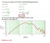
If you put a bass driver on a dipole (OB, H-frame or U-frame) and examine it's FR, you will have the bass octaves @ -20, -30 or even -40 db, virtually inaudible. A big 15 or 18 inch driver with strong motor (low Qes and big BL) would show ~100 db 100 to 500 Hz, then an OB (dipole quarter wave peak) bump of 4-6 db and then +6db diffraction step (1/2 Pi radiation pattern frequencies governed by the dimensions of the shield) AND this driver will supply a very miserable 70-80 db at 30-40 Hz, making it's lower corner frequency @-3 db not lower than 60-70-80 Hz. This would be the response of a typical ~0.2 or less Qts PA driver.
Reason: It's strong motor is handling the inertia of the membrane above Fs very well. So it is able to drive the membrane to greater amplitudes at higher frequencies thus gaining strength in SPL at greater frequencies. 100 Hz @ 10 mm p-p is allot more work than 30 Hz @ the same membrane travel... many times more work which the strong motor is capable of performing.
In the same time at low frequencies it's strong motor is experiencing difficulties supplying sufficient amplitude due to it's low Qes and big BL, it just acts as a brake - too strong grasp. - Please mention that here we are still not considering the acoustic short circuit of the dipole, we're still at the infinite baffle response. Low Qts drivers while and even though they have very strong motors, just do not supply sufficient amplitudes at frequencies near or below Fs.
Now let's see what a high Qts driver does.
Well, it just does not have the motor power to achieve great amplitudes at great speeds (higher frequencies) thus it just doesn't.
Further it's weak motor has much less damping against great cone excursions, less wire in weaker magnet and the greatest resistance met by the motor is from the suspension and from the air load.
What happens is - low frequencies raised, higher frequencies lowered.
It would still exhibit rising response towards the higher frequencies (maybe a driver with Qts of 5 wouldn't but we don't consider such drivers), but it's infinite baffle response is much flatter and it's roll off towards the bass is less steep.
Aim: to have rising HF response that is manageable with ordinary measures such as 2-nd order LP crossover.
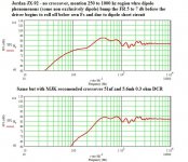
The rising HF response of a dipole is due to the sum of two things (assuming there is a flat FR region between LF roll off and the beginning of the rising) - driver natural rise and dipole quarter wave resonance*
*dipole quarter wave resonance is the FR region where front and back waves begin to sum, sum and discontinue to sum. Typically most quarter wave dipole resonances end summing just at the frequency where the driver begins to work in 2Pi space (front hemisphere - e.g. +6 db compared to the highest frequency with 360 degrees of radiation).
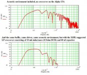
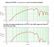
Now you have to sum driver's natural roll off, dipole roll off (acoustic short circuit), dipole peak and baffle step and you'll end with the FR of the dipole bass section. It looks quite awful, rolled off, peaked and stepped.
See attached examples of Matcad simulations of Alpha-15A and Goldwood GW1858 with and without crossovers.
2. The crossover points.
As we understood in "1" above, the LP crossover is critical for achieving a flat and decent bass response, it cuts as much as 5 to 10 db, but thus it levels the FR, eliminates the dipole peak and etc.
How about crossover points?
You could never cross a dipole woofer to a dipole midrange/extended range at one and the same frequency.
Reason: The sum of dipole induced phenomenons and the LP crossover is a flat FR for certain band above electrical crossover point and after that the woofer response begins to roll off. Thus you don't get any slope at electrical crossover point, you get it at higher frequency.
The same applies for the mid/extended range, usually it is on a baffle with width similar to the bass driver or in the case with H-frames and U-frames actually narrower than path around the frame below.
With the OB part for midrange or extended range, you do the same as with the bass driver, but in the opposite direction.
The bass crossover sums with the rising response caused by different phenomenons to extend the FR higher and in the same time to reduce some efficiency in the upper band of the bass in order to raise the relative level of the bottom octaves.
The HP crossover does the same only in the opposite direction - it will have a higher electrical crossover point which will roll off the electrical signal, but the summed acoustical output of the OB+phenomenons+crossover will be flat for some frequencies below crossover before starting to roll off.
The designer is required to design HF and LF parts of the system in such a way that their -3 or -6 db points are at one and the same frequency for flat system FR.
Such a system is impossible to design at home without the background knowledge used to write the present reply! Irrespective of any measurement equipment!
The measurement equipment is pretty useless at home due to reasons part of the common knowledge, especially in the lower octaves. A simulation is hard to read with included environment, try to figure what a mic will read.
Measuring a designed and predicted system is another story, you will know where to look.
3. Miscellaneous
- the DCR of the inductance in the LP crossover contributes for further rising of the bass driver's Qts. Might be valuable knowledge if a driver lacks just a little. The same applies for series resistance.
- the sensitivity of the extended/fr driver should be matched to the outcome of the crossover+dipole bass system below.
- Dipoles sound beautiful!
Hope that helps!
I recommend using the freeware simulation software "EDGE" from Tolvan Data for gaining of experience:
Products from Tolvan Data
Only good for HF part of a dipole system as it considers all drivers to be constant SPL sources (maybe Qts 0.707 - I'm guessing here)
A proper dipole simulation software will consider both baffle governed roll off and bass driver infinite baffle response - this is not done by the EDHE, it returns only OB response which is not a system response. It is very accurate at frequencies with wavelengths shorter than 2x the baffle width.
And I strongly recommend reading the whole site of Martin King:
Quarter Wavelength Loudspeaker Design
Best Regards!
Attachments
Last edited:

All these are simulated/assumptions/calculations and I have yet to see real life data that the generated acoustic outputs match.
Of course I too wish that building OB are that simple!
Of course I too wish that building OB are that simple!
Excuse me for the expression, but if you handle a microphone to a Chimp, it will sooner or later come up with decent sounding speakers. The same applies to a Chimp behind a typewriter, it is calculated that if you leave the Chimp 1.000.000 (one million) years with the typewriter, at some pint The "Iliad" of Homer will come out even without syntax errors. And the same applies to "tuners" with dynamometers without other background such as engineering degree, some understanding in the background and etc.
Iterative investigation is not a random action, so I do not understand the monkey analogy there.
From LinkwitzLab:
Q24 - What is your process for designing an open baffle speaker?
1 - Decide on a 2-way, 3-way or 4-way system depending upon output volume requirements, allowable size or intended application.
2 - Design and build a proto cabinet(s) with dimensions based on estimates of necessary baffle size, diffraction and aesthetics.
3 - Mount the drivers in the cabinet(s) and measure the free-space frequency response on-axis, off-axis, horizontally and vertically.
4 - If the response is not uniform, then change the cabinet dimensions. Repeat steps 3 and 4 until the response meets the target.
5 - Design and build prototype line level filters to equalize the drivers for flat on-axis response.
6 - Measure on-axis response and repeat steps 5 and 6 until target is met.
7 - Design and build prototype crossover line level filters.
8 - Measure on-axis response and repeat steps 5, 7 and 8 until targets for in-phase and out-of-phase response are met.
9 - Measure the free-space frequency response on-axis, off-axis, horizontally and vertically. If the result is not adequate, then go back to step 4.
10 - Listen to the speaker in mono using a wide range of program material and test tones.
11 - If the results in step 10 are acceptable, then build a second cabinet(s), otherwise go back to step 2 or 5.
12 - Assemble a second speaker.
etc ...
This, of course, is to assume that the goal is to build OB speakers at the performance level similar or better to Orion, etc.
All these are simulated/assumptions/calculations and I have yet to see real life data that the generated acoustic outputs match.
Of course I too wish that building OB are that simple!
Then I have to ask: Have you tried Martin's MathCAD worksheets? For the projects he has done that I've heard, and for the one OB project I did, his MathCAD worksheets predicted the results just fine.
Cheers, Jim
No. I've used and compared other simulators (Edge, ABC Dipole).
Can you point me to a project which compares the simulation and measured result with MatchCAD? As I said, I've never seen this.
Can you point me to a project which compares the simulation and measured result with MatchCAD? As I said, I've never seen this.
I haven't bothered to document my projects (including the OB). Martin's site has lots of info and then there is his quarter-wave Yahoo group.
Cheers, Jim'
Cheers, Jim'
- Status
- Not open for further replies.
- Home
- Loudspeakers
- Full Range
- OB guide/book