I am currently working with my roommate on a remote controlled passive volume control. Here is my current, first working version:
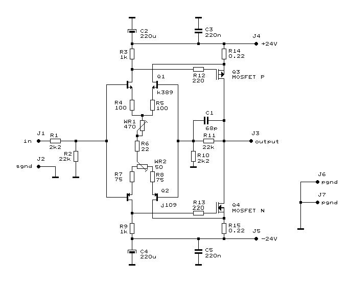
This is basically a proof of concept version, consisting of 2 channels with 4 relays per channel, giving 16 total volume steps. The design is based on 8 relays per channel, but there wasn't room on the protoboard for more then 4 for each channel. Currently, only one side of each relay is being used, but with both sides being used, it will act as a 2 channel balanced volume control with 256 steps including mute. Here is the schematic for the relay volume control:
We are currently working on the details of the project, and starting to make a pcb to accomidate all 16 relays, and the microcontroller, a PIC18F452.
Others on this forum have expressed interest in this project, as a lot of people are looking for a high quality volume control. By simply using relays and resistors, it is quite a clean volume control. Significant lengths will be taken to ensure a clean audio path on the pcb.
How many people on this forum would be interesting in making this a group project?
I could supply the finished pcb, relays, programmed microcontroller and control logic in the form of a kit. I thought about just providing pcbs, but relays and other parts are much cheaper when purchased in large quantity, and I will need to program all of the microcontrollers for this project for people anyway.
As for the remote control aspect, my roommate is working on the code for a universal learning remote control unit for it now, so that it will work with any remote control. I like this, because I like to use the unused buttons on my normal remotes for stuff like this.
As for display, I am using this display for mine:
(image from other project with it)
It costs $100, but for the kit, I am considering making it work without a display, with this display, or with a significantly cheaper lcd display (~$10).
As for using it, I am planning on using mine for two setups, one for my normal leach amp, seperate from it, and the other, integrating it in the same chassis as my bosoz.
Anyone on the forum interested in making this a group project, with my supplying of a kit for this? Any comments on what you would like in a passive volume control?
Most of the credit for this project goes to my roommate, who spent a lot of time making the first prototype for a school project this semester.
--
Brian
cool
not sure it's a practical approach for SoD (son of dork) since i need lots of 1dB attenuation steps, but the control scheme is cool. where'd you get the nice VFD?
not sure it's a practical approach for SoD (son of dork) since i need lots of 1dB attenuation steps, but the control scheme is cool. where'd you get the nice VFD?
Re: cool
Not enough steps? There are 256 steps, including mute with the 8 relays... add 2 more relays, and you have 1024 steps total. Modify the 8 resistors to get whatever resistance that you want.
I ordered the vfd direct from Noritake. Here is the page for this one:
http://www.noritake-elec.com/7000.htm
It was just under $100 shipped.
The model number is:
GU140X32F-7002
It is very useful to use, and has many advanced features over normal vfds. You can set different windows on it.
--
Brian
dorkus said:not sure it's a practical approach for SoD (son of dork) since i need lots of 1dB attenuation steps, but the control scheme is cool. where'd you get the nice VFD?
Not enough steps? There are 256 steps, including mute with the 8 relays... add 2 more relays, and you have 1024 steps total. Modify the 8 resistors to get whatever resistance that you want.
I ordered the vfd direct from Noritake. Here is the page for this one:
http://www.noritake-elec.com/7000.htm
It was just under $100 shipped.
The model number is:
GU140X32F-7002
It is very useful to use, and has many advanced features over normal vfds. You can set different windows on it.
--
Brian
Hi Brian,
I am definitely interested in this project. One thing I
really like is that this is balance is also handled, but
probably with greater ease of use than standard dual
mono attenuators.
Dennis
I am definitely interested in this project. One thing I
really like is that this is balance is also handled, but
probably with greater ease of use than standard dual
mono attenuators.
Dennis
have you figured out the optimal resistor values for precise 1dB attenuation increments? i sure haven't... i wonder if there's a mathmatical solution better than brute force (iterative).
Yes Brian, good idea to make a kit.
As I told you before I'm also interested in a set as volume control for BOSOZ. The idea of adding a display is very nice too.
I'm in for a two channel balanced vol.
Take your time is OK for Jan/Feb.
Since aparently the signal is going through the relays we maybe don't want to cheep-out on these?
As I told you before I'm also interested in a set as volume control for BOSOZ. The idea of adding a display is very nice too.
I'm in for a two channel balanced vol.
Take your time is OK for Jan/Feb.
Since aparently the signal is going through the relays we maybe don't want to cheep-out on these?
hmm
why switch the signal thru the relays? any opposition to a simple shunt control with fixed series resistor?
why switch the signal thru the relays? any opposition to a simple shunt control with fixed series resistor?
Vacuum fluorescents
there has been a seller of Noritake displays off and on -- check Businesss Equipment/Electronic Components on the Bay
there has been a seller of Noritake displays off and on -- check Businesss Equipment/Electronic Components on the Bay
dorkus said:have you figured out the optimal resistor values for precise 1dB attenuation increments? i sure haven't... i wonder if there's a mathmatical solution better than brute force (iterative).
I haven't even tried yet 🙂 Currently, it is just using 4 resistors for the proof of concept:
2k
1k
500
250
This gives 15 positions plus mute, which works fine to see how it works. I will test the next version with these values:
8k
4k
2k
1k
500
250
125
60
--
Brian
apassgear said:Yes Brian, good idea to make a kit.
As I told you before I'm also interested in a set as volume control for BOSOZ. The idea of adding a display is very nice too.
I'm in for a two channel balanced vol.
Take your time is OK for Jan/Feb.
Since aparently the signal is going through the relays we maybe don't want to cheep-out on these?
I am using NEC MR82 relays:
http://www.nec-tokin.net/now/english/product/pdf_dl/mini_data/relay_MR82_e.pdf
I will try other types of relays once to see the difference with it. I have no problems with these relays thus far. Here is the technical info for the relays:
http://www.nec-tokin.net/now/english/product/pdf_dl/mini_tech/relay_MR82_tehcdata_e.pdf
I love the Noritake 7000 series display. It is great looking, and very capable for advanced features and programming.
--
Brian
Re: hmm
I am simply following the same path as the Pass Labs P1.7 preamp used for the volume control:
http://www.passlabs.com/pdf/aleph/apserv17.pdf
I have read quite a few reviews of the revision 2 saying that it worked great as a volume control. I see no problems with it. It works great, and is a whole hell of a lot better then the PGA2310.
--
Brian
dorkus said:why switch the signal thru the relays? any opposition to a simple shunt control with fixed series resistor?
I am simply following the same path as the Pass Labs P1.7 preamp used for the volume control:
http://www.passlabs.com/pdf/aleph/apserv17.pdf
I have read quite a few reviews of the revision 2 saying that it worked great as a volume control. I see no problems with it. It works great, and is a whole hell of a lot better then the PGA2310.
--
Brian
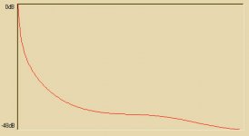
I made a plot of attenuation (in dB) vs. steps for the P1.7 volume control - it isn't even close to logarithmic. Note that a logarithmic response would appear as a straight line in this plot. Near 0dB attenuation, the step size is the largest, at about 4dB.
For 8 relays, the maximum possible attenuation is 48dB. The resistor values in the P1.7 design are already optimized - changing any of the values results in step discontinuities in the plot.
Also interesting to note is that it isn't obvious how to switch the relays - it's not just a simple binary count. It took me a while to figure it out. For the first half of the range, you count up from zero in steps of two. For the second half of the range, you count down from 255 in steps of two.
Craig
Attachments
Re: Vacuum fluorescents
I have seen this, but they are not the newest 7000 series displays from Noritake, which are absolutely great. They have a lot of advanced features that makes them harder to program, but very capable. They have a great windowing feature that allows you to set windows and talk to each of the seperately, so that if you want to just change one thing on the display, you don't have to fool with the rest. This solves the text positioning issues of other displays. The picture above from the alarm clock has 3 seperate windows being used. I haven't programmed it myself, as my roommate did all of the code for this project, but he is in love with it, and wants to purchase one for himself soon, once I take this one back from him to use for myself.
If anyone finds the Noritake 7000 series displays for cheaper then $100, let me know. I was quite hesitant of purchasing such an expensive display, but you really have to see it in person to see how beautiful it is. It is also very easy to see from across the room with the double sized fonts.
--
Brian
jackinnj said:there has been a seller of Noritake displays off and on -- check Businesss Equipment/Electronic Components on the Bay
I have seen this, but they are not the newest 7000 series displays from Noritake, which are absolutely great. They have a lot of advanced features that makes them harder to program, but very capable. They have a great windowing feature that allows you to set windows and talk to each of the seperately, so that if you want to just change one thing on the display, you don't have to fool with the rest. This solves the text positioning issues of other displays. The picture above from the alarm clock has 3 seperate windows being used. I haven't programmed it myself, as my roommate did all of the code for this project, but he is in love with it, and wants to purchase one for himself soon, once I take this one back from him to use for myself.
If anyone finds the Noritake 7000 series displays for cheaper then $100, let me know. I was quite hesitant of purchasing such an expensive display, but you really have to see it in person to see how beautiful it is. It is also very easy to see from across the room with the double sized fonts.
--
Brian
i would go variable shunt/fixed series
cleaner, better sounding, easier to implement. input impedance varies a lot, but who cares.
i think the VFD is worth every penny. just make sure to put it in a separate chassis, or shield it really well, i hear they are quite noisy.
cleaner, better sounding, easier to implement. input impedance varies a lot, but who cares.
i think the VFD is worth every penny. just make sure to put it in a separate chassis, or shield it really well, i hear they are quite noisy.
csd said:I made a plot of attenuation (in dB) vs. steps for the P1.7 volume control - it isn't even close to logarithmic. Note that a logarithmic response would appear as a straight line in this plot. Near 0dB attenuation, the step size is the largest, at about 4dB.
For 8 relays, the maximum possible attenuation is 48dB. The resistor values in the P1.7 design are already optimized - changing any of the values results in step discontinuities in the plot.
Also interesting to note is that it isn't obvious how to switch the relays - it's not just a simple binary count. It took me a while to figure it out. For the first half of the range, you count up from zero in steps of two. For the second half of the range, you count down from 255 in steps of two.
Craig
I haven't yet heard 8 relays yet, but by using 4 relays, it sounds alright, just using a simple binary count. Once I get a board done with 8 relays, I will see how the best way to control the software. If you are going by 2 for the count, this makes no reason to include the lsb relay....
This is a work in progress, but I suspect that the P1.7 setup will work fine for my application.
--
Brian
Relay volume control
Your work is interesting, please keep us informed. I am planning a preamp/crossover, but won't begin until I finish the Aleph 4 under construction. What I really need is a multichannel device since my stereo is part of my video system. Also I would like to control back ground music in the house. So I may be looking at 8 to 10 channels with input, gain, and crossover functions.
Don
don, check out the Son of Dork preamp threads. it's been idle for a while but it outlines the design criteria for a multichannel preamp. my system is hybrid audio/video as well, so i set out to build a multichannel preamp for SACD playback, as well as integration with a surround sound system.
Brian,
In MHO the relays you propose look great (NEC RM82). But in the other hand I have little experiance with these devices.
So from my point of view go ahead whith these ones. You don't need to test others if you find these don't degade the sound. If you do test others (time consuming) I'm sure you would end trying to hear differences the same as if you were trying to decide on which 2" cable to use for a signal.
apassgear said:Brian,
In MHO the relays you propose look great (NEC RM82). But in the other hand I have little experiance with these devices.
So from my point of view go ahead whith these ones. You don't need to test others if you find these don't degade the sound. If you do test others (time consuming) I'm sure you would end trying to hear differences the same as if you were trying to decide on which 2" cable to use for a signal.
Is the DPDT relay footprint the same for most all relays? If it is, that I can make it so that you can input any voltage for the relays to use to trigger on, and then this would allow people to use whatever relays that they want to use.
Does the voltage of the relay make any difference? I am just using 5v relays for the ease of a single supply, but I can make the layout so that you can use any voltage to trigger the relays if desired.
--
Brian
- Status
- Not open for further replies.
- Home
- General Interest
- Everything Else
- Relay-based passive volume control project