 How do I fix that?
Hi Ryssen,
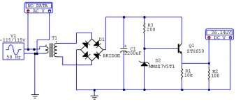
You can try a 1000k between secondary and ground and /or use more realistic diodes for the bridge,
or You download from here
http://www.linear.com/designtools/softwareRegistration.jsp
Lt-SwitcherCAD.
Here You find many examples/tutorials:
http://groups.yahoo.com/group/LTspice
Regards
Heinz!
You can try a 1000k between secondary and ground and /or use more realistic diodes for the bridge,
or You download from here
http://www.linear.com/designtools/softwareRegistration.jsp
Lt-SwitcherCAD.
Here You find many examples/tutorials:
http://groups.yahoo.com/group/LTspice
Regards
Heinz!
Ryssen. I too have had problems with transformers in cm. I don't know what it is. If you remove the transformer and replace it with the sig gen adjusted to what you expect the secondary voltage to be, you'll be right.
If you want to incorporate leakage inductance and DCR, you'll need discreet components.
If you want to incorporate leakage inductance and DCR, you'll need discreet components.

"CircuitMaker is no longer sold or supported by phone or email by Altium. For information regarding Altium's current products for complete electronic product development, visit www.altium.com. "
"Why do I get SPICE errors when I place a Transformer in my circuit?
Every node in a circuit must have a DC path to ground. Transformer isolates one section of the circuit from the rest of the circuit. Therefore, you must ensure that there is still a DC path to ground for both sections of the circuit. This can be done in various ways:
Place a ground device directly on both sides of the transformer.
Connect a high value resistor in parallel with the transformer.
Connect a high value resistor to ground on the floating side of the transformer.
Use the RSHUNT option in the Analog Options dialog box to place a high value resistor between all circuit nodes and ground."
http://www.circuitmaker.com/support/tech_faq.htm
Regards
Heinz!
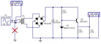
You know, it's the strangest thing. I've been using cm for years, and have always 'worked around' the transformers. Now I try this and it works 
So you need a resistor across the winding (I don't think the sig gen counts), and also a ground connection. BTW I connected both windings to my main ground.
The winding inductance also needs to be adjusted.
Thanks powerbecker (for stating the obvious)
")
So you need a resistor across the winding (I don't think the sig gen counts), and also a ground connection. BTW I connected both windings to my main ground.
The winding inductance also needs to be adjusted.
Thanks powerbecker (for stating the obvious)
Hello,
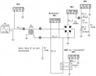
I downloaded CM from a site in Poland, and tried it for my self, its a little bit hard to work with it and will prefer SW-Cadiii or even my old ewb5.1.
But CW also does this job, but to measure the secondary a had to
"isolate" the multimeter with a VcVs, here is my circuit:
I downloaded CM from a site in Poland, and tried it for my self, its a little bit hard to work with it and will prefer SW-Cadiii or even my old ewb5.1.
But CW also does this job, but to measure the secondary a had to
"isolate" the multimeter with a VcVs, here is my circuit:
Attachments

I just simmed your circuit and got it to work. I used the: Transformers/Subcircuit/Trans1 (10TO1). I grounded one side of the primary but didn't need a resistor. The diodes work as expected.
One problem I sometimes have is wires that are not connected. Check for black dots, and use Simulation/Check_Pin_Connections on the menu bar. Sometimes a wire is broken through moving components around, but it isnt shown as an error. (Sometimes half my circuit will ride at the rail voltage because my ground buss has a break in it I can't see.)
Grabbing a component and moving it a pixel will force it to reform its connections when in doubt.
Not sure what version you are using, I don't recognise the probes. I usually set transient analysys in the analysis setup, then put the probe on what I want to see.
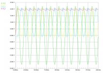
Wait on, they look like DMM's. At turnon, you will get very low voltages, I think you need to use the transient view and the probe tool to see the rise and ripple.
Wait on, they look like DMM's. At turnon, you will get very low voltages, I think you need to use the transient view and the probe tool to see the rise and ripple.
- Status
- This old topic is closed. If you want to reopen this topic, contact a moderator using the "Report Post" button.
- Home
- General Interest
- Everything Else
- Trying to learn Circuit maker