POPULAR ELECTRONICS: Consumer Electronics and Experimenter magazine
9, 1969
https://worldradiohistory.com/Archive-Poptronics/60s/69/Pop-1969-09.pdf
7MB PDF file
Also: SWTPC Articles in Popular Electronics
9, 1969
https://worldradiohistory.com/Archive-Poptronics/60s/69/Pop-1969-09.pdf
7MB PDF file
Also: SWTPC Articles in Popular Electronics
Attachments
Last edited:
Correction printed in Feb 1970 Letters.
However your board appears to be much later. (What a fun collection of '558 chips.)
Last edited:
I waited 40 years... a few more weeks won't matter
Thanks for the feedback. Anyone else reading this thread... If you happen to have the schematic for the SWTPC QX-3 4-channel color organ board (using 5558 op-amps), I would really appreciate seeing a copy of it! Meanwhile, I'll keep muddling my way through trouble shooting.
Thanks!
Mark
Thanks for the feedback. Anyone else reading this thread... If you happen to have the schematic for the SWTPC QX-3 4-channel color organ board (using 5558 op-amps), I would really appreciate seeing a copy of it! Meanwhile, I'll keep muddling my way through trouble shooting.
Thanks!
Mark
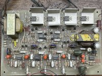
As a matter of fact, I do have the manual for the SWTPC QX3 or QXIII or QX-III. It's a scan of a copy of a copy, at higher resolution than is really necessary, in pdf form, zipped because of attachment size limits. Thanks for posting the picture of the real thing; my board is a copy that passed through various hands before I finally drilled it and stuffed most of the components.
Attachments
Last edited:
The key to making a really good sound to light box is AGC, so you don't have to keep adjusting the gain as the music envelope changes. The QX-3/QX-III/QXIII (all three are found in the manual) does that with a JFET TIS58; it also appears to have zero voltage switching, which reduces EMI when the triacs switch on. (I seem to remember EMI from light dimmers being audible on AM radios.)
Be EXTREMELY careful with this as the ENTIRE circuit is hot. The only thing that 'saves' it is the audio input transformer.
IF you need to troubleshoot you WILL need an isolation transformer. Adding 4 optocouplers, 1 for each channel would
isolate the signal side from the lamp load side. Removing the wire from the primary to the center tap of the secondary
would get rid of the problem AND IT IS A PROBLEM!!!
G²
IF you need to troubleshoot you WILL need an isolation transformer. Adding 4 optocouplers, 1 for each channel would
isolate the signal side from the lamp load side. Removing the wire from the primary to the center tap of the secondary
would get rid of the problem AND IT IS A PROBLEM!!!
G²
Presumably SWTPC sourced an audio transformer that has an appropriate amount of isolation between primary and secondary. I'd be wary of using just any old audio transformer made in recent years. If I can ever dig my unfinished QX3 out of storage, I'll try to make it work with LEDs at a safer 12V. I suspect that changing the zero voltage switching frequency to a few kilohertz would allow the LEDs to be modulated without annoying flicker.
It would make a LOT of sense to simply re-engineer the output block to isolate it from the signal block. You're talking
4 triac optoisolators for around a buck a piece (DigiKey price) and 3 or 4 resistors per output and suddenly it's
totally safe to measure with a scope and you can toss the audio transformer rather than worry if it's good enough.
G²
4 triac optoisolators for around a buck a piece (DigiKey price) and 3 or 4 resistors per output and suddenly it's
totally safe to measure with a scope and you can toss the audio transformer rather than worry if it's good enough.
G²
Thanks for the tip! I did change the line chord to a three-pronger to assure that "white" is neutral on the board.
You have a lot of faith that the hot and neutral didn't get swapped somewhere. I KNOW it isn't supposed to happen
yet it sometimes DOES.
G²
- Status
- This old topic is closed. If you want to reopen this topic, contact a moderator using the "Report Post" button.
- Home
- General Interest
- Everything Else
- Need SWTPC Psychdelia I schematic