Hello everyone. I am designing a tube opto compressor from scratch and I would like some advice from people that already worked with this. The schematic is shown below.
I am using a 6DJ8 triode tube for the gain and buffer stages, with 200V supply voltage from a transformer. The upper part of the circuit is the sidechain, which processes the signal to turn on a LED that will light the LDR in the gain stage.
The thing that bothers me the most right now is the coupling inductors, since I've never used them before. If I connect the output inductor to ground (the light blue connection), it becomes a high pass filter and compresses most of my signal below 1 kHz. Is there a workaround I can do to fix this?
Besides that, I would like to know, if there's anything that looks wrong in this circuit. Assuming I would connect it to my laptop (I know, heresy) and it has an impedance around 10 kOhms, could it work right or should I add another layer of... I dunno, reliability?
Overall, I would like any guidance that you judge necessary assuming I would build and test this the way it is. Thanks in advance!
The coupling inductors bring in problems you would not have without them. Input HP cutoff-frequency depends directly from source impedance. Output cutoff-frequency depends directly from cathode impedance i.e. 1/S. Assuming S=5mA/V=200R results in fc=100Hz approximately. The ratio of wire resistance to inductance is inappropriate for audio applications - is this a small common mode choke for rf-frequencies?
Last but not least I do not see any benefit at all from using xformers in this application.
From my experience with LDR ages ago I remember these can be very slow responding devices.
Last but not least I do not see any benefit at all from using xformers in this application.
From my experience with LDR ages ago I remember these can be very slow responding devices.
There should be a coupling capacitor between the cathode of the second section of the 6DJ8 and the output transformer.
The anode voltage of the first section of the 6DJ8 will be 90 to 100 V. Because of the voltage divider of 820K and 250K, the grid voltage of the second section of the 6DJ8 will be about 20 to 25 V. The cathode will settle at a higher voltage than the grid, but not that much higher (I estimate about 5 volt higher). This means that the voltage between cathode and anode will be about 170 V. But the datasheets give 130 V as maximum.
What will be the impedance of the full wave rectifier? It will be part of the load for the first section of the 6DJ8 so it should not be too low.
I can't say anything about the solid state circuitry, since my knowledge on that is poor.
Compressor redesign
Thanks for the reply, everyone!
I've read your suggestions and modified the design of the compressor. First, I've worked on the bias of the tubes, mainly changing the second (cathode follower) stage tube to an AC coupled topology. This way, I can address the high cathode-to-anode voltage - now it should be around 105V. Between the two tube stages, there'll be a 1M potentiometer for make-up gain, labelled "Volume".
Indeed, the full wave rectifier had an input impedance of around 10 kOhms. Hence, I will put a buffer stage (high input impedance) in the sidechain input. Thanks Robert for the heads up.

Also, I will probably remove the coupling inductors, as I've only put them in the first place as a coupling method. My question is: Is it ok to connect the circuit to and audio board with only coupling capacitors in the input and output, assuming I have high input impedance (MOhms) and low output impedance (around 1k). Is there any risk of blowing up my computer's board?
Again, I want to thank you for taking the time to help me! Any further suggestion is more than welcome.
Thanks for the reply, everyone!
I've read your suggestions and modified the design of the compressor. First, I've worked on the bias of the tubes, mainly changing the second (cathode follower) stage tube to an AC coupled topology. This way, I can address the high cathode-to-anode voltage - now it should be around 105V. Between the two tube stages, there'll be a 1M potentiometer for make-up gain, labelled "Volume".
Indeed, the full wave rectifier had an input impedance of around 10 kOhms. Hence, I will put a buffer stage (high input impedance) in the sidechain input. Thanks Robert for the heads up.
Also, I will probably remove the coupling inductors, as I've only put them in the first place as a coupling method. My question is: Is it ok to connect the circuit to and audio board with only coupling capacitors in the input and output, assuming I have high input impedance (MOhms) and low output impedance (around 1k). Is there any risk of blowing up my computer's board?
Again, I want to thank you for taking the time to help me! Any further suggestion is more than welcome.
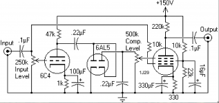
C4 (1n) looks very low in value to me. Without having calculated it, I would think something like 100n would be better.
I don't know why you want the (now) volume pot, and the connection to the sidechain, to operate in a 'dc-world' (and as a result have current flowing through the pot to ground). More normal would be to place a coupling capacitor between the anode of the first triode section and the pot/sidechain (100n). The rectifier is going to rectify the ac (signal) only, and the cathode-follower stage is not dc-coupled anymore anyway.
Now the cathode of the second triode section will sit at about 95 V. Be sure to use the appropriate triode section of the 6DJ8 when you build/breadboard it. The section with pins 1, 2, and 3 can stand 130 Vdc between heater and cathode, the other section only 50 V.
One more suggestion: Because R4 doesn't have a capacitor over it, the gain in the stage is about 15 to 20 (an estimation). With a capacitor over R4 (something like 100 uF), the gain will be about 20 to 25 (again an estimation).
I would think that more gain in that stage will give more 'room' for the compression acting on it.
I would think that more gain in that stage will give more 'room' for the compression acting on it.
C4 (1n) looks very low in value to me. Without having calculated it, I would think something like 100n would be better.
I don't know why you want the (now) volume pot, and the connection to the sidechain, to operate in a 'dc-world' (and as a result have current flowing through the pot to ground). More normal would be to place a coupling capacitor between the anode of the first triode section and the pot/sidechain (100n). The rectifier is going to rectify the ac (signal) only, and the cathode-follower stage is not dc-coupled anymore anyway.
Now the cathode of the second triode section will sit at about 95 V. Be sure to use the appropriate triode section of the 6DJ8 when you build/breadboard it. The section with pins 1, 2, and 3 can stand 130 Vdc between heater and cathode, the other section only 50 V.
The capacitance was a very low value indeed. I've calculated the high pass band and with 100n it's already enough, as you've said.
About the capacitor position, I was losing the right bias in simulation when changing it to the gain stage anode. After adding the buffer stage on the sidechain and keeping the C4 (but changing the value to 100n), it finally worked in the simulation. The power dissipated in the potentiometer was about 9 mW, but of course your suggestion is way better and I will keep it.
Also, thanks for the info about the two different voltage limits, I had no idea about that!
One more suggestion: Because R4 doesn't have a capacitor over it, the gain in the stage is about 15 to 20 (an estimation). With a capacitor over R4 (something like 100 uF), the gain will be about 20 to 25 (again an estimation).
I would think that more gain in that stage will give more 'room' for the compression acting on it.
At first I decided removing the bypass capacitor because in my mind I didn't need gain since it's not an amplifier per se, just a compressor. But your argument of headroom makes sense, so I will calculate a bypass capacitor and see how it goes.
Why complicate your life?
IF it were a VariMu compressor, of course you need tubes, but for an LDR *optical* one, just go Solid State.
No tube goodness added here, get it somewhere else, and here get the compressing job done in a more practical way.
Ok, I will try to give a little background, also in hope that it explains some of my (maybe) ignorance in the subject:
I am finishing my electrical engineering bachelor's degree, and this Compressor is my final project, suggested by my professor that is very much fond of audio engineering. This final project is split in 2, and after you present the first part, there's no going back, and I presented the first part titled as "vacuum tube compressor". Problem is, as soon as I started the second part, my professor had to leave uni and I struggled to keep contact with him. I had little to no background in audio and so this is my first audio project ever, and I am kinda on my own (in the sense that there's no one else that works with audio in my uni), learning from books and also from you guys. I am enjoying the process and I do hope I can do better projects in the future. But lately I've started a really engaging internship (nothing related with audio though) and I am having little time to invest in the project, but I need to finish it until the deadline so I can graduate. I know there are many things I could improve in this design, and I intended to do so in the beginning, but right now I have few resources to do an ideal compressor. Summing up, this stuff is expensive and hard to find where I live, I have few equipment to work with, and time is short right now. I hope one day I can spend more time exploring the audio engineering scenario and buy some different tubes to play with, and use them the proper way lol. Anyways, feel free to help me whenever you guys feel I could change something. I appreciate and take into account each and every of your suggestions, considering my available resources. Thanks for the helpful tips, I am learning a lot!
C4 (1n) looks very low in value to me. ...
Yes, except as-is the load is bootstrapped and may be many Megs effective.
I'd grab a 0.1u because the plan is clearly not finalized yet and a later design change may make that 1n cap way too small.
Tudo bem amigoOk, I will try to give a little background, also in hope that it explains some of my (maybe) ignorance in the subject:
I am finishing my electrical engineering bachelor's degree, and this Compressor is my final project, suggested by my professor that is very much fond of audio engineering. This final project is split in 2, and after you present the first part, there's no going back, and I presented the first part titled as "vacuum tube compressor". Problem is, as soon as I started the second part, my professor had to leave uni and I struggled to keep contact with him. I had little to no background in audio and so this is my first audio project ever, and I am kinda on my own (in the sense that there's no one else that works with audio in my uni), learning from books and also from you guys. I am enjoying the process and I do hope I can do better projects in the future. But lately I've started a really engaging internship (nothing related with audio though) and I am having little time to invest in the project, but I need to finish it until the deadline so I can graduate. I know there are many things I could improve in this design, and I intended to do so in the beginning, but right now I have few resources to do an ideal compressor. Summing up, this stuff is expensive and hard to find where I live, I have few equipment to work with, and time is short right now. I hope one day I can spend more time exploring the audio engineering scenario and buy some different tubes to play with, and use them the proper way lol.
")
I also have problems finding "unusual" stuff here
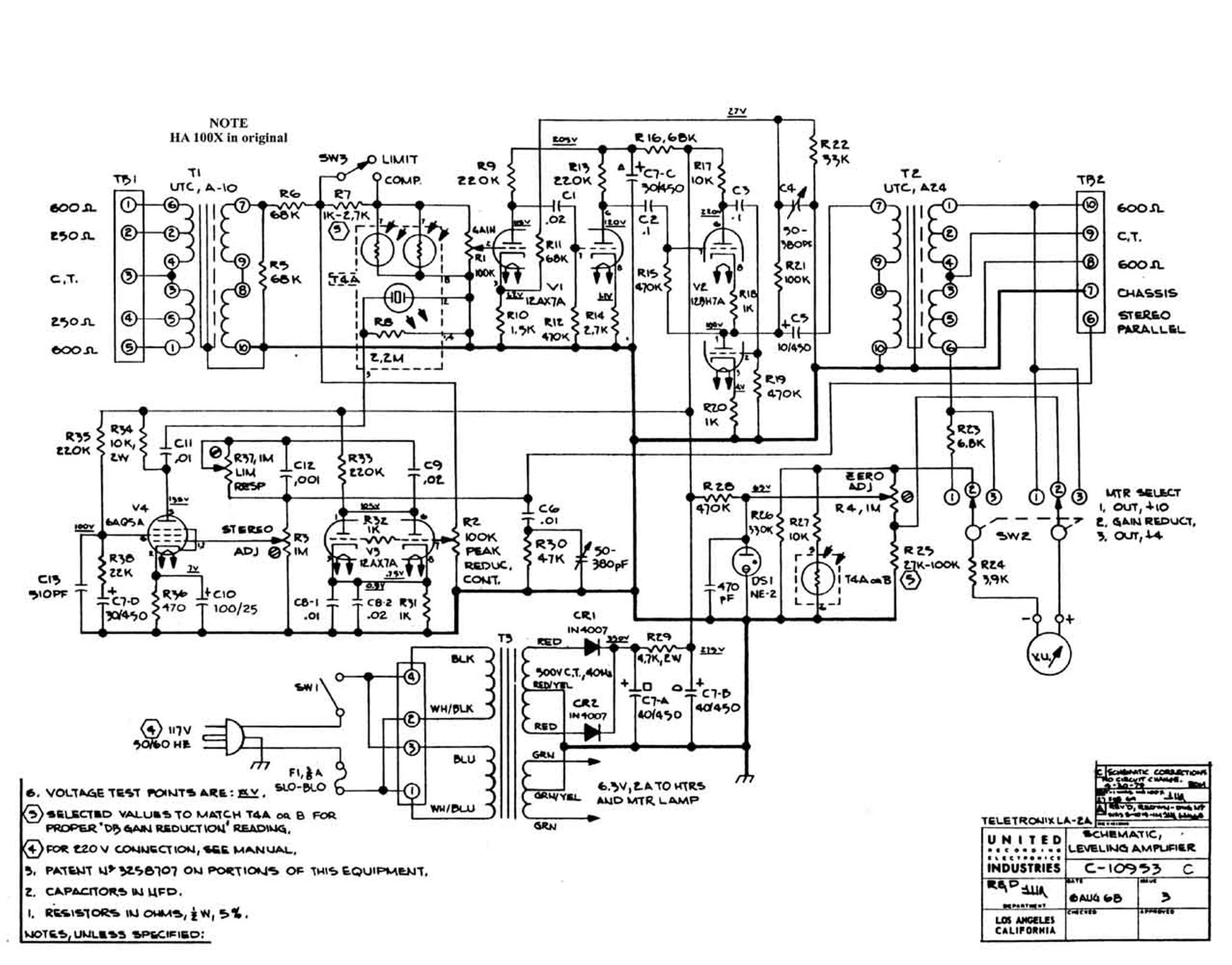
I suggest you study the classic Tube Optical Compressor which is considered "the" reference one, and still much used today, The Teletronix/UREI LA-2
Not to clone it, but as a reference.
They use a piece of unobtainable (specially in Brazil or here in Argentina) electroluminiscent panel to illuminate the CDS cell and rely on cell´s built-in time constants for attack and decay, I guess you would use some kind of Led panel.
FWIW I DO regularly use optical compressor/limiters in my own Bass Amplifiers.
Teletronix LA-2A clone for recording studio
Yes, except as-is the load is bootstrapped and may be many Megs effective.
I'd grab a 0.1u because the plan is clearly not finalized yet and a later design change may make that 1n cap way too small.
Yes, you're right, it was a mistake. The cathode follower has indeed very high input impedance.
Tudo bem amigo
I also have problems finding "unusual" stuff here
I suggest you study the classic Tube Optical Compressor which is considered "the" reference one, and still much used today, The Teletronix/UREI LA-2
Not to clone it, but as a reference.
They use a piece of unobtainable (specially in Brazil or here in Argentina) electroluminiscent panel to illuminate the CDS cell and rely on cell´s built-in time constants for attack and decay, I guess you would use some kind of Led panel.
FWIW I DO regularly use optical compressor/limiters in my own Bass Amplifiers.
Teletronix LA-2A clone for recording studio
That's interesting. I have seen some material about the LA-2A but got pretty intimidated by its design
. I will check it more closely now, though.In my design, I encapsulated a LED and a LDR together with heat shrink and applied voltage, measuring the LED's current and LDR's resistance. Then, I took note of the values and later on I could plot a function of the set. I added the equation to LTSpice's resistor and could get some pretty nice visual results, with a drum sample. I've put a very low threshold so I could see the difference between input (blue) and output (green) more clearly. You can identify the bass drum, then some hi-hats and then the snare.

Problem is, this method doesn't take into account the time dynamics of the LED/LDR set. Anyway I will have to build it to figure it out. I just wanted to share my work.
Gracias por los consejos hermano!
- Status
- This old topic is closed. If you want to reopen this topic, contact a moderator using the "Report Post" button.
- Home
- General Interest
- Everything Else
- Tube opto compressor design