Hello All,
Once again I would appreciate some guidance from the many experts on the forum.
Back in 1989 I bought two Luxman T-117 tuners. One has been in daily use ever since. The second has been in a closet for at least 10 years. I recently thought I would set up the second one for use in my office. When powered up, no display showing signal strength or frequency selected. The unit appeared to be able to be tuned, but the sound was very distorted.
I opened the unit up, and visual inspection indicated two electrolytics with signs of leakage. One capacitor C001 (1000 µF/25VDC ) was the main power supply smoothing capacitor feeding a IC voltage regulator (L79N). I have the Service Manual for the T-117, which indicated this is a +12 V device. I measured the output and got 10.7VDC. I replaced C001 with the closest matching device I had on hand (1000µF / 50 VDC). This brought the main power supply back to 12 VDC, and now I had normal sound, and tuning control, but still no display.
The second problematic capacitor C007 (18mF / 5.5VDC) associated with a circuit block identified as “5V for memory back up.” I have replaced it with the closest thing I had available (3,300µF / 50VDC). Still no display.
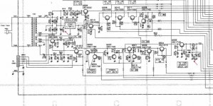
The Service Manual is 24Mb, typical for the Japanese of that era, very detailed and complete, but too large to put on the forum. I have copied the schematic for the power supply and marked (with arrows) the two capacitors just discussed.
I measured the emitter voltage on Q1001 at 2.6VDC, the manual says it should be 4.17VDC, the schematic indicates this to be a +5V rail. So, I am unsure how to proceed, I could just start replacing the larger electrolytic caps, for example C008, even though I do not understand what the circuit block it is associated with is supposed to do. The connector CB001 connects to the circuit card containing the LCD display.
Any guidance would be greatly appreciated.
Cheers,
ceulrich
Once again I would appreciate some guidance from the many experts on the forum.
Back in 1989 I bought two Luxman T-117 tuners. One has been in daily use ever since. The second has been in a closet for at least 10 years. I recently thought I would set up the second one for use in my office. When powered up, no display showing signal strength or frequency selected. The unit appeared to be able to be tuned, but the sound was very distorted.
I opened the unit up, and visual inspection indicated two electrolytics with signs of leakage. One capacitor C001 (1000 µF/25VDC ) was the main power supply smoothing capacitor feeding a IC voltage regulator (L79N). I have the Service Manual for the T-117, which indicated this is a +12 V device. I measured the output and got 10.7VDC. I replaced C001 with the closest matching device I had on hand (1000µF / 50 VDC). This brought the main power supply back to 12 VDC, and now I had normal sound, and tuning control, but still no display.
The second problematic capacitor C007 (18mF / 5.5VDC) associated with a circuit block identified as “5V for memory back up.” I have replaced it with the closest thing I had available (3,300µF / 50VDC). Still no display.
The Service Manual is 24Mb, typical for the Japanese of that era, very detailed and complete, but too large to put on the forum. I have copied the schematic for the power supply and marked (with arrows) the two capacitors just discussed.
I measured the emitter voltage on Q1001 at 2.6VDC, the manual says it should be 4.17VDC, the schematic indicates this to be a +5V rail. So, I am unsure how to proceed, I could just start replacing the larger electrolytic caps, for example C008, even though I do not understand what the circuit block it is associated with is supposed to do. The connector CB001 connects to the circuit card containing the LCD display.
Any guidance would be greatly appreciated.
Cheers,
ceulrich
End Note
Hello All,
Just an end note for those that may be following this thread.
I continued to work this problem and found that the Service Manual did not exactly match my unit. Transistors Q1001 and Q1002 are supposed to be mounted on a separate PCB, however, my unit did not have that PCB, and the two transistors are not to be found anywhere. In addition, the pin connections for connector CB001 are in reverse order for my unit, pin 1 goes to ground.
I went ahead and replaced capacitor C009, and presto, the display came to life. The tuner is again working normally, I am listening to it as I write this and it sounds great. Not bad for a 30 year old tuner.
Cheers,
ceulrich
- Status
- This old topic is closed. If you want to reopen this topic, contact a moderator using the "Report Post" button.