I'm pretty sure the crux is in the factors in the transfer equation, but I am not knowledgeable enough to 'see' it ...
Jan
Jan
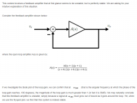
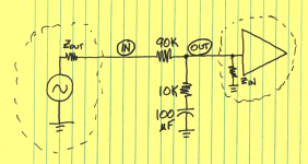
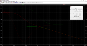
In my opinion, the circuit in Figure 1 below has the following transfer function
as long as the driver has sufficiently low Zout and as long as the receiver has sufficiently high Zin.
{intuition: at very low frequencies, the capacitor is an infinite impedance so Vout is the same as Vin. At very high frequencies, the capacitor is ~zero impedance so the circuit is a two-resistor voltage divider: Vout = (1/10) * Vin}
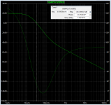
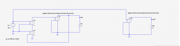
Two of these in cascade (with buffering!!) will have both of the zeroes and two of the three poles, from the given transfer function. Adding a gain of 10X and another pole, achieves the given transfer function.
I did so in LTSPICE, see Figure 2 below. Gain never exceeds 20dB (10X) which is not surprising given the transfer function. I am unable to replicate their claim that the magnitude of gain is 36 dB anywhere. Simulated phase margin is a pathetic 14 degrees, see the crosshairs. Just barely stable.
I won't rob you of the joy of constructing such a simulation yourself. It's a delightful little "etude".
_
Vout/Vin = 1.0 * (s + 1) / (s + 0.1)
as long as the driver has sufficiently low Zout and as long as the receiver has sufficiently high Zin.
{intuition: at very low frequencies, the capacitor is an infinite impedance so Vout is the same as Vin. At very high frequencies, the capacitor is ~zero impedance so the circuit is a two-resistor voltage divider: Vout = (1/10) * Vin}
Two of these in cascade (with buffering!!) will have both of the zeroes and two of the three poles, from the given transfer function. Adding a gain of 10X and another pole, achieves the given transfer function.
I did so in LTSPICE, see Figure 2 below. Gain never exceeds 20dB (10X) which is not surprising given the transfer function. I am unable to replicate their claim that the magnitude of gain is 36 dB anywhere. Simulated phase margin is a pathetic 14 degrees, see the crosshairs. Just barely stable.
I won't rob you of the joy of constructing such a simulation yourself. It's a delightful little "etude".
_
Attachments
In my opinion, the circuit in Figure 1 below has the following transfer function
Vout/Vin = 1.0 * (s + 1) / (s + 0.1)
How do you get that from the given equation??
Jan
How do you get that from the given equation??
Yikes, when changing from (Ks + 1) format to (s + (1/K)) format, I forgot to adjust the constant! Off by a factor of ten, 3 times. Thus 20dB becomes 80dB as gdan shows. blush!

Good thing I wrote "In my opinion" rather than something with greater swagger ...
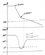
The original circuit shown by Jan has a negator at the feedback subtraction point so it is negative feedback at low frequencies. The issue is conditional stability. A good textbook will explain it in terms of poles and whether the (-1,0) point is inside or outside the loop gain locus. I have never seen an 'intuitive' explanation.
I think it would have been far clearer to present the frequency response graph as part of the question. Point out that (a) there is a range of frequencies on this plot where phase shift around the loop is zero, and also gain exceeds 1. (b) Nyquist analysis states the amplifier is stable. Then ask for an intuitive explanation.
_
_
Attachments
It would be nice if someone came up with a good answer, I don't know any intuitive explanation for conditional stability either.
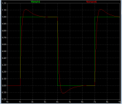
Attached is a simple demonstration circuit for conditional stability. Reduce loopgain by turning back the potmeter and ringing gets worse and worse until it oscillates.
Attached is a simple demonstration circuit for conditional stability. Reduce loopgain by turning back the potmeter and ringing gets worse and worse until it oscillates.
Attachments
As Osvaldo writes, this is one that makes sense looked at in a Nyquist plot rather than a Bode plot. The poles/zeros are bounded by the closed loop gain it will work at*, but it doesn't encircle -1. I'm bad at this stuff, so please don't make me explain it better, or you'll know just how little I understand. 😉
*as long as the loop disturbances are small, this will be stable.
** pretty sure JCX talks about his super-duper composite amps being conditionally stable. It's just hanging out with 100+ dB of loop gain at the phase margin violated frequencies, there's not a big enough hammer to make it go unstable. Even into clipping.
Maybe conditional stability has been sent to teach us that the mathematics of engineering structures is more important and has greater predictive power than intuition.
Ha, a perfect example of the "phase matters only at the intercept" thing I mentioned in the Groner/Polak composite opamp thread https://www.diyaudio.com/forums/ana...amuel-groners-super-opamp-13.html#post5796830, post#129This is a circuit for a competition for IEEE students. The task is to write an intuitive explanation/understanding of max 4 pages.
How would you guys explain this, intuitively?
Jan
It is not intuitive to me, never will be, why something can be stable when the feedback is effectively positive and the gain is > 1 at this point. I've read the Graeme appnote a hundred times, I understand the simple math he uses for the stability criterion, but heck no, it's not intuitive.
I think, because I never tried it, amplifier stability can be easily visualised and imagined with the use of two dimensional vectors. If one finds a scheme how phasors change with frequency, one should be able to decide whether sustained oscillations take place or not. Two dimensional vectors are not that difficult to mentally visualise.
I don't think vectors are sufficient. When conditional stability is present the vectors of gain and feedback tell us that oscillation will occur, but it doesn't.
- Status
- Not open for further replies.
- Home
- General Interest
- Everything Else
- Show your circuit understanding (advanced)