Hell i am new to this for some bare with me and sorry if this is in the wrong section. anyways i am rebuilding a Panasonic sa-ht80 that i had in storage for some years and i thought be a good first project anyways i was wondering what my options would be to increase power and sound quality i am sorta new to the audio world but have some solding experience this system uses the following ics posted below i dont even know where to start any help would be greatly appreciated
DVD SERVO P.C.B. [M](RTL)
REP2084D DAC, CONNECTOR P.C.B. [M](RTL)
REP2578A-N MOTOR, CD DETACT, SPINDLE
POSITION P.C.B.
[M](RTL)
REP2945C DVD, TUNER, DSP P.C.B. [M]
(RTL)E/E
B/EG
REP2945E DVD, TUNER, DSP P.C.B. [M]
(RTL)EE
REP2946C PANEL, MIC,POWER SWITCH,
SPEAKER P.C.B.
[M](RTL)
REP2944C POWER P.C.B. [M](RTL)
REP2943C AC TRANSFORMER, AC INLET
P.C.B.
[M](RTL)
INTEGRATED CIRCUITS
TA7291P IC DRIVE [M]
LA1833NMNTLM IC IF & MPX [M]
LC72131MDTRM IC PLL [M]
M62433AFP IC AUDIO [M]
M5218AP IC BUFFER AMP [M]
M5228FPE1 IC QUAD OP AMP [M]
M5218AFPE3 IC [M]
M5228FPE1 IC QUAD OP AMP [M]
M62444FPE1 IC 4CH VOL [M]
M38504M6211F IC MECHA CONTROL [M]
RSN311W64-P IC [M]
M38199MF231F IC UCON [M]
M5218AFPE3 IC [M]
M5228FPE1 IC QUAD OP AMP [M]
FA7612NTE2 IC DC/DC CONVERTER [M]
LM2940T5M IC REGULATOR [M]
M5218AFPE3 IC [M]
TC9472F-001 IC DSP [M]
BU4053BCFE2 IC ANALOG SW [M]
M5218AFPE3 IC [M]
BU4053BCFE2 IC ANALOG SW [M]
M5218AFPE3 IC [M]
T87CH47U1E42 IC DSP UCON [M]
PCM1734EB-E2 IC D/A CONVERTER [M]
PCM1734EB-E2 IC D/A CONVERTER [M]
PCM1734EB-E2 IC D/A CONVERTER [M]
TC74HCT7007A IC 3V-5V LEVEL SHIFT
[M] AN3581S-E1 IC VIDEO OUT
power specs
n AMPLIFIER SECTION
RMS TTL POWER OUTPUT 300 W
(10% total harmonic distortion at 1 kHz)
FRONT 36 W per ch (6W)
CENTER 36 W (6W)
SURROUND 36 W per ch (6W)
SUBWOOFER 120 W (6W)
DIN TTL POWER OUTPUT 220 W
(1% total harmonic distortion at 1 kHz)
FRONT 26 W per ch (6W)
CENTER 26 W (6W)
SURROUND 26 W per ch (6W)
SUBWOOFER 90 W (6W)
Input sensitivity/ input impedance
AUX 250 mV, 10 kW
n FM TUNER SECTION
Frequency range 87.5 - 108.0 MHz (50 kHz steps)
Sensitivity 16.3 dBf (1.8 μV, IHF)
Antenna terminals 75 W unbalanced
n AM TUNER SECTION
Frequency range 522 - 1629 kHz (9 KHz steps)
Sensitivity
S/N 20 dB at 999 kHz 500 μV
Pick up
Beam Source Semiconductor Laser
Wavelength 665 nm
n GENERAL
Power supply AC 230-240 V, 50 Hz
Power consumption 178 W
Standby 0.50 W
Hi Jeff, and welcome to diyAudio ")
Hmmm... the brutal answer (sorry) is that this isn't really the kind of equipment suited to much modification. You won't be able to increase the power output, that is fixed by the supply voltages used internally.
The only IC's out of those that we would even consider looking at would be the 'opamps' but tbh, your not going to gain much at all by changing those when looked at in the whole scheme of things.
Ultimately, the overall sound quality is limited by the unit as whole, and there is so much processing and routing of the audio as it negotiates all the circuitry that its not possible to isolate any one section and say its a problem. I think you would find it very difficult to work on to.
Probably not what you wanted hear but I'm afraid in this case, the options are very very limited indeed.
thanks so for the response its not what i wanted to hear but i would rather have a truthful reply as soon as i opened it up i knew it had complex circuits then after locating the service manual i got even more lost so nothing can be replaced/upgraded? if i remember correctly last time i had it working it did have really good sound quality it just got really hot. or would it be possible to just use utilize main power board and dsp? and get rid of the transverse deck and am/fm tuner card. i just thought instead of tossing it i would dismantle and clean it and whiel i had it apart see if there was anything i could update or fix.
The likely need to change the power transformer and heatsink, probably the two largest things in the case, and also possibly the case...
This would amount to a rebuild all the same. Each component would need to be examined for suitability to an upgrade of power. The question of sound quality is another story even.
What you might be better doing is making the proposed mods in a new case, ie beginning a new amp. It may be possible to keep the pre stages of your existing amp.
Whatever you decide, good luck.
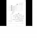
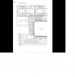
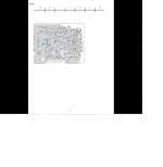
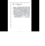
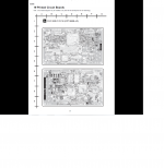
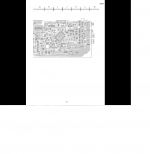
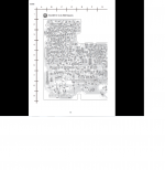
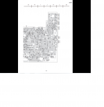
Thanks for the replies sorry i did not post the schematics before. it slipped my mind i spent all night cleaning old flux off of the boards. i sent it in under warranty in 2001 for repairs was having problems with the video also had it in for service a couple times out of warranty to have the disk drive adjusted and the laser cleaned. after replacing some leaking caps a year ago i just decided to put it off to the side and get a new one. i seen it the other day and thought it would make a good project to clean up and refinish. i was looking though my parts bin and found a 800 watt amp board i also found some computer power supplies would i be able to pull a decent transformer out of one of those? i attached the schematics i inspected all the boards when i was cleaning them up and everything looks good i will be refinishing the chassis components tomorrow and will post some photos thanks jeff
sorry there unorganized.
Attachments
-
 panasonic 1.png325.2 KB · Views: 109
 -
 panasonic 10.png113.4 KB · Views: 54
 -
 panasonic 9.png107.5 KB · Views: 57
 -
 panasonic 8.png106.4 KB · Views: 79
 -
 panasonic 7.png85.3 KB · Views: 53
 -
 panasonic 6.png72.2 KB · Views: 46
 -
 panasonic 5.png91.3 KB · Views: 112
 -
 panasonic 4.png89.1 KB · Views: 106
 -
 panasonic 3.png108.7 KB · Views: 195
 -
 panasonic 2.png93.7 KB · Views: 105
>>>
Attachments
-
 panasonic 20.png173.6 KB · Views: 50
 -
 panasonic 19.png220.1 KB · Views: 48
 -
 panasonic 18.png157.4 KB · Views: 43
 -
 panasonic 17.png155.2 KB · Views: 32
 -
 panasonic 16.png163.2 KB · Views: 37
 -
 panasonic 15.png206.6 KB · Views: 38
 -
 panasonic 14.png89.8 KB · Views: 36
 -
 panasonic 13.png65.8 KB · Views: 31
 -
 panasonic 12.png89.5 KB · Views: 63
 -
 panasonic 11.png103.9 KB · Views: 52
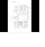
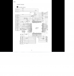
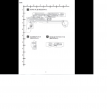
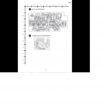
here are just the boards i have the block diagrams and circuit layouts to if you need them theres alot though
Attachments
-
 panasonic 59.png173.2 KB · Views: 39
 -
 panasonic 60.png197 KB · Views: 42
 -
 panasonic 61.png114.7 KB · Views: 33
 -
 panasonic 62.png190.1 KB · Views: 36
 -
 panasonic 58.png141.3 KB · Views: 32
 -
 panasonic 57.png152.3 KB · Views: 32
 -
 panasonic 56.png78.2 KB · Views: 30
 -
 panasonic 55.png176.9 KB · Views: 51
 -
 panasonic 54.png331.5 KB · Views: 43
 -
 panasonic 53.png151.2 KB · Views: 43
Ouch. I'm pretty happy with 10W and most would be good with 100W (you'll get it straight about such things around here800 watt amp
)No. Switched mode supplies. No conventional power transformers.computer power supplies would i be able to pull a decent transformer out of one of those?
They can be a good source of the following: IEC mains connectors, RFI suppression components/mains filters, ferrite chokes, high voltage diodes, schottky diodes, sometimes interesting transistors, small heatsinks, occasionally a gapped iron choke, maybe some high voltage film capacitors, a couple of higher voltage electrolytic capacitors.
sorry that was a typo i meant type 135w i was so tired i did not catch it thanks for the info my main goal is cooling and make sure is has the power it needs i think the main problem is cooling when i replaced the bad caps on the main power board i remember heaving to re flow alot of joints because they flowed togetherOuch. I'm pretty happy with 10W and most would be good with 100W (you'll get it straight about such things around here
No. Switched mode supplies. No conventional power transformers.
They can be a good source of the following: IEC mains connectors, RFI suppression components/mains filters, ferrite chokes, high voltage diodes, schottky diodes, sometimes interesting transistors, small heatsinks, occasionally a gapped iron choke, maybe some high voltage film capacitors, a couple of higher voltage electrolytic capacitors.
Ok thank you for the advise I'll see if a can pick up some 35v capacitors also quick question I noticed none of the ic's or transistors have heatsinks on them would these be worth heats inking ? I mean there inches from the transformer also if I do add heatsinks would I have to ground them? I Did notice a lot of the caps on the boards are Samsung brand and I have not had luck with them in other equipment so I may just see what capacitor s I have on hand and replace them all so I don't have to worry about it
All good Jeff, I was only putting in my 2c anyway.
Heat at the smoothing capacitors isn't a good sign. They're usually worth replacing.
Generally if they didn't have them in the original design, you should be ok. If you run the amp for long enough for it to reach a thermal equilibrium and switch it off, ensure the large caps discharge to a safe level and keep yourself at chassis potential, you can feel them. If you can keep your hand on them that's a good sign.
Smaller capacitors tend to have less exposure to large ripple currents and on average are less likely to be a concern.
Smaller capacitors tend to have less exposure to large ripple currents and on average are less likely to be a concern.
the reason i ask is because i have to order the caps because nobody carries them where i live so i was also going to order heat sinks to replace the stock pressed one on 2SB651ARTA and 2SB621ARSTA i also was going to add a heat sink to LM2940T5N because these hang right over the smoothing capacitors and when the dvd player is on these get really hot so i think by adding finned heat sinks and a additional one to LM2940T5N this will help disperses the heat towards the exhaust fan instead of the power board but on the stock pressed heat sink for 2SB651ARTA and 2SB621ARSTA it has tabs that have grounds on the bottom of the board and i am unsure if i use mica insulators and screw insulators if i still need to ground them also i was planning on replacing the thermal paste of the main amps because the stock is a bit excessive what kind would you recommend? i have some ic diamond left from a recent computer build but don't know if that is good for amps or should i use some plain silicone based stuff?
Just speaking broadly, there are some tricks and tips that might help.
Heat shields are sometimes useful (like the ones you might see hanging off the back of a modern slow combustion wood heater chimney there to protect the wall).
Air flow baffles (tunnel walls) can improve air flow in some instances, where a fan is an important part of a design to begin with (which isn't something I do with my own amps in case they fail).
Changing a heatsink looks simple but can be fiddly and might present a risk to the components in the process, so go as slow as you need. Another option is to bolt a helper heatsink on to the existing one or improve airflow instead.
Although heatsink grease has worse thermal conductivity than the parts it is joining, at least there is some there. If you're going to change it, the metallic kind is interesting but normal silicone grease works well. You need to keep in mind that normal grease is dielectric, and some transistors need to be electrically isolated from the heatsink (eg maybe the heatsink is grounded or there are multiple devices on the one sink.
- Status
- This old topic is closed. If you want to reopen this topic, contact a moderator using the "Report Post" button.
- Home
- General Interest
- Everything Else
- need help on options