The item in question is a generic replacement battery pack for an 7/8 year old Acer laptop. The laptop is 100% good and the original battery is fine apart from gradual loss of running time.
I managed to get a new generic replacement which "worked" once although it never reached 100% charge and beyond around 80% charge the charge light was flashing red/green. The run time was good... once. Next recharge and it was dead. No output at all. I got the battery swapped.
The replacement seemed to be the same with the flashing lights but it did reach 100% eventually. It performed well for a couple of full charge/discharge cycles and then like the other went dead. The battery is marked with the same part number as the original.
At this point let me say that my knowledge of these "smart batteries" is only what I have gleaned from the web... and there seems to be a lot of information and mis-information out there 🙄
So in disgust I cracked the new dead (but showing 100% fully charged by the Windows battery meter) pack open and measured 12.65 volts across the cells. From my limited understanding, that is the absolute max point that three 3.6 or 3.7 volts cells can be taken too. So fully charged then. The original pack has the cell voltage permanently enabled on the outer pins of the socket. The new pack at this point has zero voltage between the outer pins.
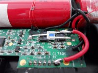
The positive battery lead goes first to this mystery part (and no where else) and I was expecting one of the other leads to go to the +11.1 volt main output but it doesn't. I can only assume it goes to the chips underneath it. The middle pin of this part goes via very thin print (so no current flow) to the logic and what seems like a driver transistor.
For the pack to be dead, I suspect the logic on the board has "turned off" a series FET somewhere.
At this point I linked the plus battery feed to the pack outlet pin and thought "what the heck", lets try it. That is the red wire tagged on to the part. The PC boots OK, the battery meter shows the correct level and falls (I only tried for a few minutes) and on connecting the charger it shows as charging and reaches 100%. Hmmm....
There is actually current flow in the new red lead under quiescent conditions. Around 0.4ma for a second or two, then it drops, then it pulses again.
So here is the part,

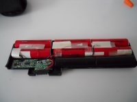
Here is an overview of the pack,

I would like to know what that part is if anyone has any idea 🙂
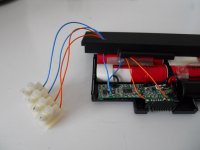
And finally, the last question for now. My next step is to confirm the battery charges and then cuts off OK. I might solder two wires to this resistor which is in series with the battery negative, and monitor the current that way,

What value is it ? I'm thinking its 0.01 ohm because my DVM doesn't want to know and my ancient AVO8 shows some resistance is there but that its way under 0.1 ohm. I could pass a fixed current through it and determine it that way I suppose.
I managed to get a new generic replacement which "worked" once although it never reached 100% charge and beyond around 80% charge the charge light was flashing red/green. The run time was good... once. Next recharge and it was dead. No output at all. I got the battery swapped.
The replacement seemed to be the same with the flashing lights but it did reach 100% eventually. It performed well for a couple of full charge/discharge cycles and then like the other went dead. The battery is marked with the same part number as the original.
At this point let me say that my knowledge of these "smart batteries" is only what I have gleaned from the web... and there seems to be a lot of information and mis-information out there 🙄
So in disgust I cracked the new dead (but showing 100% fully charged by the Windows battery meter) pack open and measured 12.65 volts across the cells. From my limited understanding, that is the absolute max point that three 3.6 or 3.7 volts cells can be taken too. So fully charged then. The original pack has the cell voltage permanently enabled on the outer pins of the socket. The new pack at this point has zero voltage between the outer pins.
The positive battery lead goes first to this mystery part (and no where else) and I was expecting one of the other leads to go to the +11.1 volt main output but it doesn't. I can only assume it goes to the chips underneath it. The middle pin of this part goes via very thin print (so no current flow) to the logic and what seems like a driver transistor.
For the pack to be dead, I suspect the logic on the board has "turned off" a series FET somewhere.
At this point I linked the plus battery feed to the pack outlet pin and thought "what the heck", lets try it. That is the red wire tagged on to the part. The PC boots OK, the battery meter shows the correct level and falls (I only tried for a few minutes) and on connecting the charger it shows as charging and reaches 100%. Hmmm....
There is actually current flow in the new red lead under quiescent conditions. Around 0.4ma for a second or two, then it drops, then it pulses again.
So here is the part,
Here is an overview of the pack,
I would like to know what that part is if anyone has any idea 🙂
And finally, the last question for now. My next step is to confirm the battery charges and then cuts off OK. I might solder two wires to this resistor which is in series with the battery negative, and monitor the current that way,
What value is it ? I'm thinking its 0.01 ohm because my DVM doesn't want to know and my ancient AVO8 shows some resistance is there but that its way under 0.1 ohm. I could pass a fixed current through it and determine it that way I suppose.
Attachments
At this point let me say that my knowledge of these "smart batteries" is only what I have gleaned from the web... and there seems to be a lot of information and mis-information out there 🙄
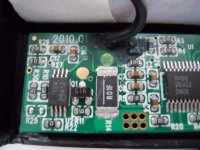
I have read that replacing cells in a dead pack is pointless because of some secret chip (that makes sure the pack isn't over (dis)charged) that doesn't reset and allow full use of the new cells. Could it be some sort of microprocessor battery monitor that can be reprogrammed?
Hi Ron,
And there looks to be a lot of "secret" chips in this thing lol. I think you are probably right in that it can be programmed but how that would/could be done is probably like the chips... a closely guarded secret.
I've been Googling away for the last half hour or so, and searching Google images has just turned up something interesting. The part appears to be a thermal fuse that can triggered to fail open circuit by the logic. I've never seen or heard of these devices before tbh.
Something About Energy: M520GBAT
Now in my case, there was certainly no over temperature event. So it seems like its been triggered by the logic. I wonder if the charge points are a fraction to high ? not that I can alter that anyway. That's another thing I don't really understand. Is it the laptop hardware that terminates the charging or is it the battery smart chip and its internal FET switch ? I just don't know.
Tomorrow, and I might try linking it out (which will still give a dead battery as it is now) and seeing if the logic will reset when placed on charge.
Why do things like this have to be so complicated 😀
(swapping cells... I did read that many of the smart chips need a constant power source to them and that you have to "keep them alive" when swapping cells... and worse than that... if there is multiple monitoring of the cells then they have to be disconnected/reconnected in the correct sequence)
This is becoming an adventure in learning about Li-Ion batteries. I attached wires to the 0.01 ohm with a view to monitoring the current, both charging and discharging. I also connected wires to the pack output voltage terminals.

The pack was fully charged so I powered up the laptop and monitored the current which settled to around 1.65 amps. It was fascinating watching the current shoot up as you click on something, opening a pdf, clicking an email notifier and so on. It spiked at around 3.3 amps regularly. The voltage was 12.34 volts at the start and I'm monitoring it and making notes.
The battery meter works and seems to behave normally when discharging.

Now for the really interesting bit. I discharged the pack a few percent as a test and then connected the charger. I expected the laptop to level out the charge voltage at a maximum of around 12.6 volts but no... and this had me alarmed at first... the voltage rose to 16.8 volts, then dropped, then 16.8 again and so on. The current was around 3.3 amps in this pulsed state. However the duty cycle of the pulses (the non charge period) gradually got longer and longer. 10 seconds, 20 seconds, a minute. After around 30 minutes it was around 2 seconds charging and 6 minutes not. There also seemed to be a another voltage applied to the battery toward the end. It would go from say 12.3 to 12.7 volts for a second or two. No obviously measurable current flowed at this time. Then it would do the high current pulse thing again and so on. After the 30 minutes the charging stopped altogether and the battery voltage settled at 12.3 ish.
I was alarmed by this seemingly high voltage charging but found this which is interesting,
Patent US6040684 - Lithium ion fast pulse charger - Google Patents
This seems to show that pulse charging (and as such greatly exceeding the normal "safe" voltage maximum") is a recognised technique.
The upshot of all this and the conclusions I have drawn are that the non manufacturer produced packs are flawed in the firmware programmed into the "smart chip" in the battery.
I'll hopefully show the results of the full charge and discharge later.
The pack was fully charged so I powered up the laptop and monitored the current which settled to around 1.65 amps. It was fascinating watching the current shoot up as you click on something, opening a pdf, clicking an email notifier and so on. It spiked at around 3.3 amps regularly. The voltage was 12.34 volts at the start and I'm monitoring it and making notes.
The battery meter works and seems to behave normally when discharging.
Now for the really interesting bit. I discharged the pack a few percent as a test and then connected the charger. I expected the laptop to level out the charge voltage at a maximum of around 12.6 volts but no... and this had me alarmed at first... the voltage rose to 16.8 volts, then dropped, then 16.8 again and so on. The current was around 3.3 amps in this pulsed state. However the duty cycle of the pulses (the non charge period) gradually got longer and longer. 10 seconds, 20 seconds, a minute. After around 30 minutes it was around 2 seconds charging and 6 minutes not. There also seemed to be a another voltage applied to the battery toward the end. It would go from say 12.3 to 12.7 volts for a second or two. No obviously measurable current flowed at this time. Then it would do the high current pulse thing again and so on. After the 30 minutes the charging stopped altogether and the battery voltage settled at 12.3 ish.
I was alarmed by this seemingly high voltage charging but found this which is interesting,
Patent US6040684 - Lithium ion fast pulse charger - Google Patents
This seems to show that pulse charging (and as such greatly exceeding the normal "safe" voltage maximum") is a recognised technique.
The upshot of all this and the conclusions I have drawn are that the non manufacturer produced packs are flawed in the firmware programmed into the "smart chip" in the battery.
I'll hopefully show the results of the full charge and discharge later.
Attachments

"secret chip"
I had the same experience in multiple Li ion replacements .
A lot of notebook battery packs have a build in EEprom that stores the battery wear . If you change the cells the notebook or the battery pack still reads the wear and wont charge the battery to full charge 😡
There are guides on the net how to reprogram the EEproms , but it's all SMD and you have to take them of the PCb's and solder them back in !
Cheers ,
Rens
Last edited:
Thanks 🙂 There is a myriad of info out there but its great to hear your practical experiences of this. My pack as it stands now is the "new one". I didn't fancy cracking the old open in case I ended up with two duffers 😀 although I did consider maybe transplanting these cells into the old one. So it seems that might not successful anyway from what you say.
As long as I feel this one is safe then I'll leave it as it is I think. We're still running, one hour fiveteen mins in and still showing 46% and an hour left. Voltage down to 10.65 and current average has gone from 1.64 to 1.83 as you would expect.
As long as I feel this one is safe then I'll leave it as it is I think. We're still running, one hour fiveteen mins in and still showing 46% and an hour left. Voltage down to 10.65 and current average has gone from 1.64 to 1.83 as you would expect.
Its the individual cell voltages that is monitored for impending failure.
If one of the cells differs from the others by a specified amount, the monitoring chip basically says time up and burns off the Three-Terminal Fuse.
I don't know the allowed variation, but its pretty small.
Its possible for one cell to go dangerously overvoltage if the other cells are low, so thats the reason for this.
Ah, I hadn't realised it might use cell voltages to trip the fuse. I only monitored the total pack voltage when charging. The behaviour of the laptop charge LED is incorrect too when using these replacement packs in that it changes to a flashing LED at around 65% fully charged. It also never changes to a constant "green" showing full, even though the charge cycle has been confirmed as stopping.
I thought a bit more about the high voltage I was observing and figured that this was a result of measuring at the pack terminals rather than across the cells directly. From what I have been able to piece together from observations, it is the FET switches in the pack that open and close to allow what is essentially a constant current pulse of up to 16 volts to be applied to the cells. When I see the meter kick up to 16 volts, this will be the FET's opening and what I am reading is the laptop output voltage. The laptops output voltage must also be controlled somehow, not perhaps in voltage but on or off because otherwise I would see this high voltage all the time... and yet that doesn't happen.
The sequence in pulse mode (which is after around 65% fully charged) seems to be,
1) Charge at constant current and when cell voltage reaches some value the battery FET's turn off.
2) At this point I read over 16 volts, but this is the open output of the laptop charge circuit.
3) The voltage falls to a "rest value" which will correspond to the cell voltage. In so doing the laptop output must have been switched "off" presumably be the battery.
4) The charge pulse cycle resumes and each cycle takes the final "rest" voltage of the pack that little bit higher.
5) When the pack voltage at rest exceeds say 12.65 volts then the whole process stops as the pack is fully charged.
That's how it all appears to me as I watched and monitored it. The cells remained cool throughout. It also gave me the chance to measure current consumption while altering the screen brightness. At minimum it drew around 1.6 amp and on max 2.1 amp. I was quite surprised it was big a difference tbh. That is with a CFL display.
All very interesting......


- Status
- Not open for further replies.
- Home
- General Interest
- Everything Else
- Laptop Battery I.D. Mystery Part and Questions.