I tried asking this over at the ESP forum, but that forum is quite quiet after it's new format.
In the ESP project,
Distortion Analyzer (notch filter) , there are two opamps.
I want to use AD797's. I have these already soldered up, but I have 2 questions about the 797's....
1) Would I use any of the 797's Distortion Cancellation and Bandwidth Enhancement" (pin 8) scheme ?
2) If I wanted to trim the DC offset, how would I measure the offset?
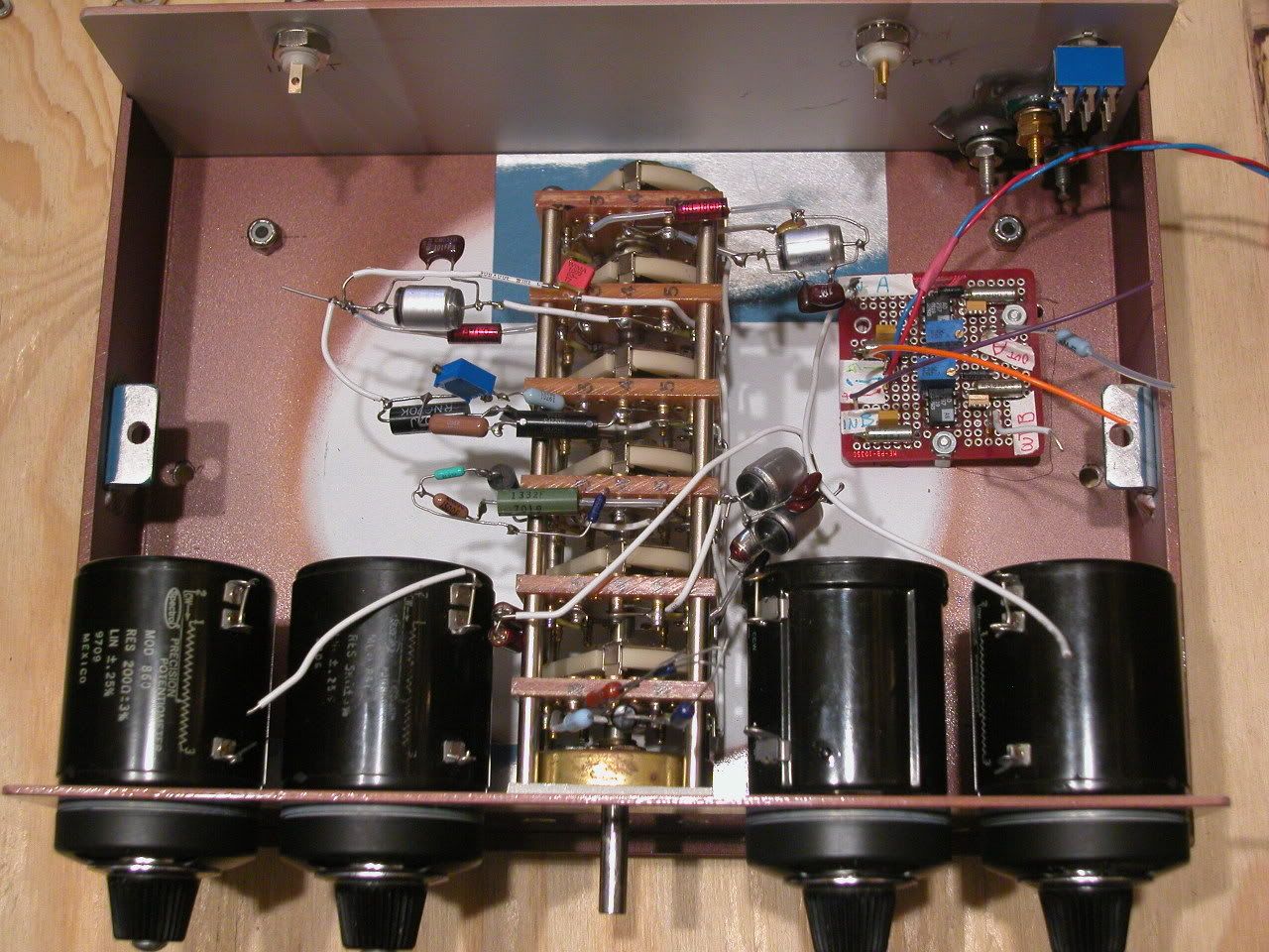
Right now, I have a small circuit board and these parts installed (pic below, only one opamp shown) , so the notch filter parts are not connected yet (but are finished as well). I am VERY confused regarding HOW TO CHECK the offset, to trim it.
Thanks,
=RR=
In the ESP project,
Distortion Analyzer (notch filter) , there are two opamps.
I want to use AD797's. I have these already soldered up, but I have 2 questions about the 797's....
1) Would I use any of the 797's Distortion Cancellation and Bandwidth Enhancement" (pin 8) scheme ?
2) If I wanted to trim the DC offset, how would I measure the offset?
Right now, I have a small circuit board and these parts installed (pic below, only one opamp shown) , so the notch filter parts are not connected yet (but are finished as well). I am VERY confused regarding HOW TO CHECK the offset, to trim it.
Thanks,
=RR=
You should have posted in Solid State
Scott Wurcer, the designer of AD797 is more often there.
But he will come into this forum, too.
I do not think that output pin of lower OP would need to be at zero dc-offset.
The important thing is of that notch circuit is that
when IN is connected to 0V = GND
then should be as close as possible to 0.000 VDC at OUT
------------
Method a)
To trim any one of them separate, I would hook up your second piture
with 10 kohm between +IN pin and GND
and with 10 kohm between OUT pin and GND
... then adjust until OUT pin is 0.000 VDC
------------
------------
Maybe you can try this
1. Trim the lower OP using Method a)
2. Put both upper and lower in Notch Circuit
3. Attach IN terminal to GND
4. Adjust upper OP 20k trimpot until you get 0.000 VDC at OUT terminal.
Note:
I do not think you really need to do point 1.
Because the lower OP-amp will not effect the DC-offset of Notch Filter Circuit.
Hi,
I build this circuit over en over again, to optimize it..
the AD797 is not a good chooice here... really no need to try to use such an expensive opamp in that place... save it so you can use it for an low THD oscilator instead!
The notch filter filteres out most of the signal (at least 60dB, but up to 100dB is possible), .. so only a very small signal (< few mVolts) is presents at the opamp.. even with cheap 5534s or opa134s of even TL072, you would get any additional distorion...
Noise is a much more prominent problem in this circuit.. a loew noise FET imput opmpa would be ideal.. ad734 (?).. opa134..
goodluck,
Thijs
PS Why are you bothered by the DC ofset? It's a distortion measurement circuit! DC offset doesn't matter at all...
Thanks lineup, I give that a try.
tschrama ...
Thanks for the tips.
About the trim pots....I tend to put these things in whenever possible....a practice I should stop. It's less hassle to pick a low offset opamp if needed...often the better grades of a particular opamp have lower offset, and need no trimming, plus good circuit balance is usually all that is needed.
You know how some people use unnecessarily exotic caps....
well I have an addiction to trim pots.
Gotta kick it.
(click on pic)
Almost finished.
Caps matched with a General Radio 1654
=RR=
")
tschrama said:Hi,
I build this circuit over en over again, to optimize it..
the AD797 is not a good chooice here... really no need to try to use such an expensive opamp in that place... save it so you can use it for an low THD oscilator instead!
The notch filter filteres out most of the signal (at least 60dB, but up to 100dB is possible), .. so only a very small signal (< few mVolts) is presents at the opamp.. even with cheap 5534s or opa134s of even TL072, you would get any additional distorion...
Noise is a much more prominent problem in this circuit.. a loew noise FET imput opmpa would be ideal.. ad734 (?).. opa134..
goodluck,
Thijs
PS Why are you bothered by the DC ofset? It's a distortion measurement circuit! DC offset doesn't matter at all...
I meant: .. even with cheap 5534s or opa134s of even TL072, you would NOT get any additional distorion...
Furthermore the ad797 has very high current noise.. again, my advise would be to desolder the AD797, out in some opamp sockets and first try it with a couple TL071..
I just read Rods project again, and he seems to hint to use high quality opamps.. well Rod is a terrific good guy, but I have been fiddling with this schematic for days and days some more days... if you notch out the signal good, the opamps will NOT introduce distortions, even if it's a TL071
The device you are proposing to use needs special attention wrt compensation otherwise it can oscillate. Read the applications note carefully and if required apply the RC networks on the input pins.
Take th e advice given earlier - no need to use this very, very good op-amp in this application. Think about it
if your system under test distortion is 0.1% and a cheap op-amp measures this to within 5% you will get a result of between .0995 and .105 - the delta due to the non-linearity of the 'cheap' op-amp. If you now use a really good op-amp with ppb distortion, you pretty much get 0.1% . . . . so don't bust your balls for .005% error
janneman said:Nicely build-up unit. Where did you get the multiturn pots?
Local surplus store, new-old-stock.....and no, they did not cost me $20-30 each (typical eBay price).
and the Daven switch...
and the case....
....come to think about it, everything is from the surplus store except the chips and the proto board.
One of the filter frequencies I added to this notch filter is 60 Hz.
But I cannot get it to filter properly, like other freqs......maybe because of ripple from my (line powered) PSU. ???
I may try to power it from batteries, and see if that helps.
If it does, perhaps I can choose a different chip that requires a lower voltage, to keep the number of batteries to a minimum.
What is your prediction, will this help the 60 Hz notch ??
60.02 Hz
R1, R2 = 26.9 k
R3 = 13.45 k
C1, C2 = 98.5 nf
C3 = 197 nf
f = 1 / 2 * pi * R1 * C1
http://sim.okawa-denshi.jp/en/TwinTCRkeisan.htm
=RR=
In stock, I have two opamp choices that may work for a low-power battery solution.
AD822
http://www.analog.com/static/imported-files/data_sheets/AD822.pdf
TLC2201
http://focus.ti.com/lit/ds/symlink/tlc2201.pdf
Do you see a preferred device ?
(single or dual supply ?)
thanks, =RR=
AD822
http://www.analog.com/static/imported-files/data_sheets/AD822.pdf
TLC2201
http://focus.ti.com/lit/ds/symlink/tlc2201.pdf
Do you see a preferred device ?
(single or dual supply ?)
thanks, =RR=
- Status
- This old topic is closed. If you want to reopen this topic, contact a moderator using the "Report Post" button.
- Home
- General Interest
- Everything Else
- Tips for AD797 ??