Hello:
I just got my hands on a new (to me) scope. It is a fairly basic B&K model, analogue, 2 channel, 30 MHz. It seems to be in good shape. It was not expensive, so I don't have huge expectations.
It came without probes, so I purchased some cheapo units that looked decent... See the link below for reference:
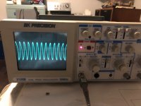
I wonder if there is an issue with this scope. If I display a trace with a considerable vertical component, the trace seems skewed at the edges of the display but not at the center. I am wondering if this is a fault, an issue of cheap probes, and if there is an obvious fix...
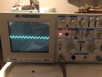
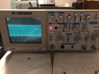
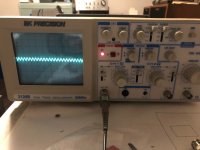
To illustrate the issue, I am posting here two pictures of a 1 kHz sine wave (one with the probe at 1 Megaohm, and again with the probe at 10 Megaohm). The same is posted with a 10 kHz wave. The results are the same.
Any ideas? Suggestions, advice are hugely appreciated.
Thank you,
David
I just got my hands on a new (to me) scope. It is a fairly basic B&K model, analogue, 2 channel, 30 MHz. It seems to be in good shape. It was not expensive, so I don't have huge expectations.
It came without probes, so I purchased some cheapo units that looked decent... See the link below for reference:
I wonder if there is an issue with this scope. If I display a trace with a considerable vertical component, the trace seems skewed at the edges of the display but not at the center. I am wondering if this is a fault, an issue of cheap probes, and if there is an obvious fix...
To illustrate the issue, I am posting here two pictures of a 1 kHz sine wave (one with the probe at 1 Megaohm, and again with the probe at 10 Megaohm). The same is posted with a 10 kHz wave. The results are the same.
Any ideas? Suggestions, advice are hugely appreciated.
Thank you,
David
Attachments
Last edited:
Agree, that looks like the deflection is misadjusted on the CRT. Nothing to do with probes. ANything your probes would distort would generally be in the vertical realm, not horizontal.
See those little "clouds" in the upper corners? To my eye that is caused by stray electrons from the beam reflecting off the sides of the tube.
See those little "clouds" in the upper corners? To my eye that is caused by stray electrons from the beam reflecting off the sides of the tube.
Agree, that looks like the deflection is misadjusted on the CRT.
Yeah. That's pretty severe astigmatism.
If you choose to attack the adjustment yourself mark the pots with a permanent marker so you can return to the original position. Get the service manual. Follow the alignment procedure (after you've done all the other checks in the manual). Don't stick your fingers on the high voltage. And beware that a probe slip can be fatal both for you and the scope. I killed an HP1345 vector display that way. At least I didn't kill myself (although I did feel like I died a little on the inside. Those displays are pretty rare).
I would check the various bias points and such before tweaking the pots, though. Follow the procedures in the service manual. It would not surprise me if something is broken (like a cap that's dried out) in the deflection circuitry.
Nothing to do with probes. ANything your probes would distort would generally be in the vertical realm, not horizontal.
Agreed. You can get distortion both vertically and horizontally with probe mis-calibration, though. But the distortion will be consistent across the screen. Not like shown in Post 1 where the edges on the left side of the screen bow one way and the edges on the right side bow the other way.
See those little "clouds" in the upper corners?
Yep! That's probably ambient light passing over OP's shoulders causing a reflection.
Tom
Thank you.
I did find a service manual and there are several calibration and test procedures. However the manual covers several models and the information provided (references to pots, components, board layouts, etc.) are all wrong. So I am still pursuing that.
The purpose of this post is to try to limit the field a bit and get pointed in the right direction. It seems this type of thing is likely a classic or familiar fault.
I am not totally convinced it is a horizontal issue though. If there vertical amplification has timing issues, I could imagine this type of distortion would result.
If I do start probing in there I will be one-handing it for sure...
Best,
D
It seems this type of thing is likely a classic or familiar fault. I am not totally convinced it is a horizontal issue though. If there vertical amplification has timing issues, I could imagine this type of distortion would result.
Not a fault, this is a misadjustment, possibly from a tweaker gone wrong.
There are internal adjustments, on the CRT itself and others, that must be done right
to have an accurate trace displayed.
A little history would be helpful. Did the scope work fine one day and the next day it didn't? Or did someone dink around with it and broke it?
If it broke from one day to the next, my money is on a bad component. Probably an electrolytic cap that's gone cranky.
I strongly doubt the vertical amp is to blame. If it was, it somehow turned itself into a time-variant system as it behaves differently at the two ends of the trace (which are separated in time by the horizontal sweep time). As my academic advisor would say, "that's either fundamentally reportable or fundamentally wrong."")
It could be the sweep circuit though. If you have a working scope, I'd look at the sawtooth that's coming out of the time base.
Tom
If it broke from one day to the next, my money is on a bad component. Probably an electrolytic cap that's gone cranky.
I strongly doubt the vertical amp is to blame. If it was, it somehow turned itself into a time-variant system as it behaves differently at the two ends of the trace (which are separated in time by the horizontal sweep time). As my academic advisor would say, "that's either fundamentally reportable or fundamentally wrong."
It could be the sweep circuit though. If you have a working scope, I'd look at the sawtooth that's coming out of the time base.
Tom
Last edited:
Just acquired. This was part of a fleet of scopes from a college that upgraded, and sold off their old ones. I doubt people were inside making tweaks. When I opened it up, there were no worn or missing screws. It looks pristine.
Sold under a description 'excellent condition'.
Sorry, but I have no other information.
Sold under a description 'excellent condition'.
Sorry, but I have no other information.
I agree with Rayma somebody has been "fiddling " with the internal adjustments to the control grids( anodes ) on the tube .
As they can be interactive it might take more than one adjustment , a linear sweep is required ( sawtooth ) , its mostly Textronik oscilloscopes I have worked on but they mainly use various internal adjustment to adjust the trace.
Watch out for high voltages --yes its sore and keep one hand in your pocket.
A service manual is available online gives a full set up procedure including horizontal adjustment.
Last edited:
What does the internally generated Cal signal look like? (accessible on the front panel)
I've never seen anything like that on a scope CRT display but someone mentioned a magnetized shield. I dunno, I really don't on that one. It all looks so symmetrical.
Astigmatism usually only has a limited range and is often set by just getting the best visual combination of that and focus together. It doesn't cause that type of weird effect.
Its bizarre.
Last thought of the day...
The low amplitude views with the divider probe on divide by 10 look OK and then with it on X1 it looks OK in the picture.
Could it be a rail issue with the higher amplitude waveform modulating the horizontal sweep supply.
Is it the same if you use Channel 2?
I'll be interested to know what this one is
The adjustment is called geometry and it should be documented in the manual. However you need to check the CRT voltages first. Is the vertical or horizontal calibration correct? The HV may be off (high) and that messes everything up. Also the bias etc. around the CRT has impact on this.
Thank you for all the responses. This is a B&K 2120B dual trace, 30 MHz. I have contacted the manufacturer and they may have some additional service documentation that I do not yet have. So I will see if I can set-up the recommended adjustments, if I get better documentation.
Testing the square wave test signal available on the front, I get a pretty respectable display of the square wave. Will post a picture later.
This edge distortion of the display is identical on both channels and always occurs only on waveforms with a significant vertical component, everything else looks perfect.
Best,
D
Last edited:
With pin-cushion distortion, I can imagine a nice looking square wave when the display has symetrical displacement above and below centerline. But what happens if you use vertical position control to get center-line to near full scale amplitude square wave? i.e. Does shape change with vertical position adjustment?Testing the square wave test signal available on the front, I get a pretty respectable display of the square wave. Will post a picture later.
- Home
- Design & Build
- Equipment & Tools
- Oscilloscope distorted waveform at edges