I have an ancient Fluke 8060a that the display has been out for many years.
I ran across it in the shop the other day. After searching the internet for an LCD display for it for most of the afternoon and coming up empty, I was about to throw it out.
There were some web pages about rewiring the leads and attaching a different LCD display, but it seemed like a lot of work. And I have two other Fluke meters, so no worries.
But before I threw it out, I decided to just take it apart and see if I could see anything obvious. There wasn't anything obvious, it was pretty clean, the board looked ok, there was very little dirt and no residue of any type that I could see.
But just for grins, I decided to clean the contact area on the LCD with alcohol, do the same for the connector side, and put it back together.
To my amazement, when put back together it works perfectly!! The LCD, which had maybe two segments you could read, is now just like brand new!
So long story to say I learned a lesson! Those old LCD displays may not fail as often as they appear. They just lose good contact and need a little cleaning.
gabo
I'm not a rabid re-capper, but experience has taught me that, with most of the well aged equipment I use, it may be a good plan.
Both of my Keithley meters (177 & 173A) recently had to be re-cap'd due to shorted electrolytics, one of which took out a pass transistor in the power supply. And to be clear, these were not cheap chinese caps, we're talking top grade parts with epoxy end seals. Clearly, nothing lasts forever!
So, figured while I'm at it, I'll do all of my meters and get it out of the way.
It turned out to be quite a list; I'd never realized just how many different meters I use for everything
There is an issue with leaking caps with these if you do some searching. Whether it was just a bad batch or not I'm not sure, but a lot of these have caps that have leaked electrolyte all over the boards. Mine was in fairly bad shape and the board was a bit beat up by the time I was done. I was surprised that it actually worked so well after I got it all back together. There are some great guides posted on refurbing these.
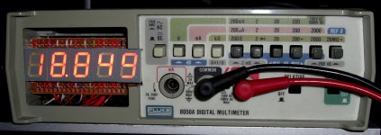
photo of a Fluke 8050A I converted to LED's
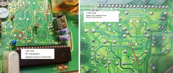
forty wires! the 7805 regulator gets a bit warmer so put a small heatsink on that (20mm bolt), increase size of unregulated supplies capacitors to 1000uF (reduce ripple),
the DP's and the -ve sign work, didn't bother with the other indicators,
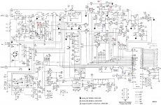
didn't like the power on/off switch because it runs the unregulated supplies right through the main PCB and the display PCB to get to the switch and the line transformer is always left on, wasn't bothered about relative measurement so the Power and Relative switches have gone,
I used common Cathode LED's and no series resistors! the leading "1" needs a little help from a pull up resistor to get the brightness right, the -ve sign needs a PNP transistor to work properly,
be careful working near the CPU chip, its very close to the unregulated supplies,
forty wires! the 7805 regulator gets a bit warmer so put a small heatsink on that (20mm bolt), increase size of unregulated supplies capacitors to 1000uF (reduce ripple),
the DP's and the -ve sign work, didn't bother with the other indicators,
didn't like the power on/off switch because it runs the unregulated supplies right through the main PCB and the display PCB to get to the switch and the line transformer is always left on, wasn't bothered about relative measurement so the Power and Relative switches have gone,
I used common Cathode LED's and no series resistors! the leading "1" needs a little help from a pull up resistor to get the brightness right, the -ve sign needs a PNP transistor to work properly,
be careful working near the CPU chip, its very close to the unregulated supplies,
Attachments
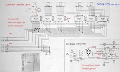
PS. the ten LED Common Cathode pins (two pins per LED) are wired to the -5V line,
wire count:-
segment wires 4x7 + 1x3
decimal point wires 4
Common Cathode wires 5
hard wire -5V and DGnd lines from main PCB to display PCB, wires 2
wires between main PCB and display PCB, W,X,Y,Z,DP,ST0,ST1,ST2,ST3,ST4, wires 10
break the unregulated lines to prevent them leaving the main PCB, break the BP wire connect it to the -5V line on the display PCB,
FLUKE 8050A bench DVM LED Display
- Home
- Design & Build
- Equipment & Tools
- Fluke 8060a