I made a little software tool for automated curve tracing, using two programmable power supplies (here). However, the power supplies are rather slow, so it's not possible to do a proper "pulse" testing, where the power is applied to the device under test (DUT) for a small fraction of a second only. The DUT may therefore heat up quite a bit, and self-heating changes the DUT characteristics during the test. This is especially important with power transistors, where a lot of heat is involved, even if the DUT is mounted on a (large) heatsink.
I managed to reduce the effect somewhat by inserting 10s long idle periods between the measurements (about 1s each). During those idle periods, the DUT is run at a fixed (high) power to keep it warm (hot). The idle periods allow the DUT+heatsink to stay hot between low-power measurement points. However, the temperature is not stable enough, and self heating is still a problem.
I guess a rather simple improvement would be to mount the DUT on a big block of copper, which would provide much more thermal inertia than a normal heatsink. I could also try to add some separate heater elements (power resistors) connected to a temp regulator. However, I don't want to re-invent the wheel! What are good approaches to keep the temperature stable during power DUT tests?
Liquid coolers are good to efficiently remove the heat from the system. But are they also good to keep the temperature constant even if the heat injected from the DUT is variable? I guess keeping the temperature constant requires two things:
(i) High heat conductance to spread the heat. This should be fine with liquid coolers.
(ii) Large heat capacity so that quick changes in the heat dissipation don't cause any large temperature changes. Are liquid coolers are good with this?
(i) High heat conductance to spread the heat. This should be fine with liquid coolers.
(ii) Large heat capacity so that quick changes in the heat dissipation don't cause any large temperature changes. Are liquid coolers are good with this?
It depends on what you want to do.
In a Class A amp, the devices is not working at room temperature.
And for some FETs, the characteristics changes quite a lot. at say 55°C case temperature
And these changes differ between devices, even from the same batch.
So the only way to have perfect matching is to match at working conditions.
And that means in continuous mode with the DUT bolted to an appropriate heatsink.
Or temperature controlled heater block.
F5 power amplifier
Patrick
It depends on what you want to do.
For matching, I see no problem. All is good as long as the DUTs are operated at the same power/dissipation and at the same heatsinking for long enogh. This will result in identical temperature conditions for the different DUTs, so the results can easily be compared for matching.
I want to achieve curve traces that are taken at (sufficiently) constant temperature. As it is now, I mount the DUT on a heatsink and then get readings at different voltages and currents, i.e., at different power dissipation. When readings are taken at low power, the DUT will be realtively cooler than when readings are taken at high power. Therefore, depending on the tempco of the DUT, the curves will be affected by the temperature change between low-power and high-power readings.
The temperature drift is avoided with short pulse testing. Howeever, this does not work with common-garden bench-top PSUs as used in my setup.
temperature controlled heater block.
F5 power amplifier
This looks interesting. How does the temperature control work?
I used a PTC heating element (60 degrees iirc) under a aluminium u channel. Toggle clamp and a bit of graphene on the surface of the Alumiunium below the toggle clamp. This helps make sure that each test is done with the same contact pressure.
Cheap, not very neat, but works very well. The sanity check is to measure the same device again after some time or some days and the curves match perfectly every time so I’m happy.
Cheap, not very neat, but works very well. The sanity check is to measure the same device again after some time or some days and the curves match perfectly every time so I’m happy.
Attachments
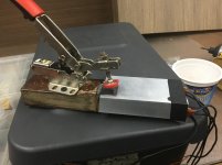
The Ptc heaters are available at multiple voltages and temperatures. If you want higher wattages than available you can double the Ptc heater element (that’s what I did) - makes for a more even temp bed. 200 watt Ptc is available but I think at higher temps.
I only used the jig for power mosfet. Turn on heater and wait till temp settles, clamp mosfet, wait till temp settles (5 mins) then curve trace. The current drawn by the Ptc might also be another nice way to determine when quiescence has been reached...
Cheers,
Ps here is an example of the Ptc: Constant Temperature Heating Plate 12V / 24V / 220 60degree AC/DC PTC Heating Plate Aluminum Large Heat Insulation Heating Plate|Cable Winder| - AliExpress
Last edited:
You need to create an environment like the transistor would see in real use.
In an amplifier it could be used at high power and so high heat.
Some of the semiconductor analysers just test at a couple of mA as the yare battery powered yet are used by repair houses for matching.
I designed my own curve tracer but used 40mA as a better test.
I guess ideally for a power amp it should be at a much higher level but 40mA is 20 times better than 2mA !
may be inapropriate thoughts but :
- thermal inertia will interfere with testing. In real life, transistors heat, so why not testing with high temp like tcxo ?
- if you want to make short measures, jigs like ones used in slewrate testing (avalanche mode, clamping...) can be a start point.
my
- thermal inertia will interfere with testing. In real life, transistors heat, so why not testing with high temp like tcxo ?
- if you want to make short measures, jigs like ones used in slewrate testing (avalanche mode, clamping...) can be a start point.
my
A pulse test or a single direction trace will never tell you the whole story, unless you operate at low Class AB.
Take this as an example :
E19 headphone amplifier board K2381 J407 MOSFET Yuanjing Audio
John Curl's Blowtorch preamplifier part II
This sort of thermal hysteresis you will never catch unless you measure at operating conditions and in continuous mode.
Even if you use a heater block, unless you continuously cycle the DUT, you will not see this.
We don't go into such trouble with our matching for no reasons.
Cheers,
Patrick
Just for info -- here's how Tektronix approached it in 1971: http://w140.com/tek_176_ocr.pdf
I designed my own curve tracer but used 40mA as a better test.
The programmable power supplies I have will happily output 15 A up to 20 V or higher...

thermal inertia will interfere with testing.
How? Why?
In real life, transistors heat...
That's exactly the point! But the question is how to keep the temperature constant during the test. See OP.
if you want to make short measures, jigs like ones used in slewrate testing (avalanche mode, clamping...) can be a start point.
Sure, but my question is about something else. My setup uses programmable power supplies, which are way to slow for short pulse testing. I am looking for methods to keep the temperature constant using my power-supply setup.
- Status
- This old topic is closed. If you want to reopen this topic, contact a moderator using the "Report Post" button.
- Home
- Design & Build
- Equipment & Tools
- Curve tracing of power transistors: how to control temperature?