Hi Everyone ")
I've a little question about measurement of an DIY amplifier First Watt with an Oscilloscope ...
I've build a dummy load ( 8Ohm / 50W ) , and buy Hameg Oscilloscope for testing Amp.
::: Test situation :::
View attachment 772979
::: Square form evolution :::
100mV Offset / 1 min
View attachment 772980
60mV Offset / 10 min
View attachment 772981
20mV Offset / + 20 min
View attachment 772982
View attachment 772983
Square form look like (J) exemple on the last pic.
It's a normal wave form for you with 1Khz square under 8Ohm load ?
Thank you
Sancho
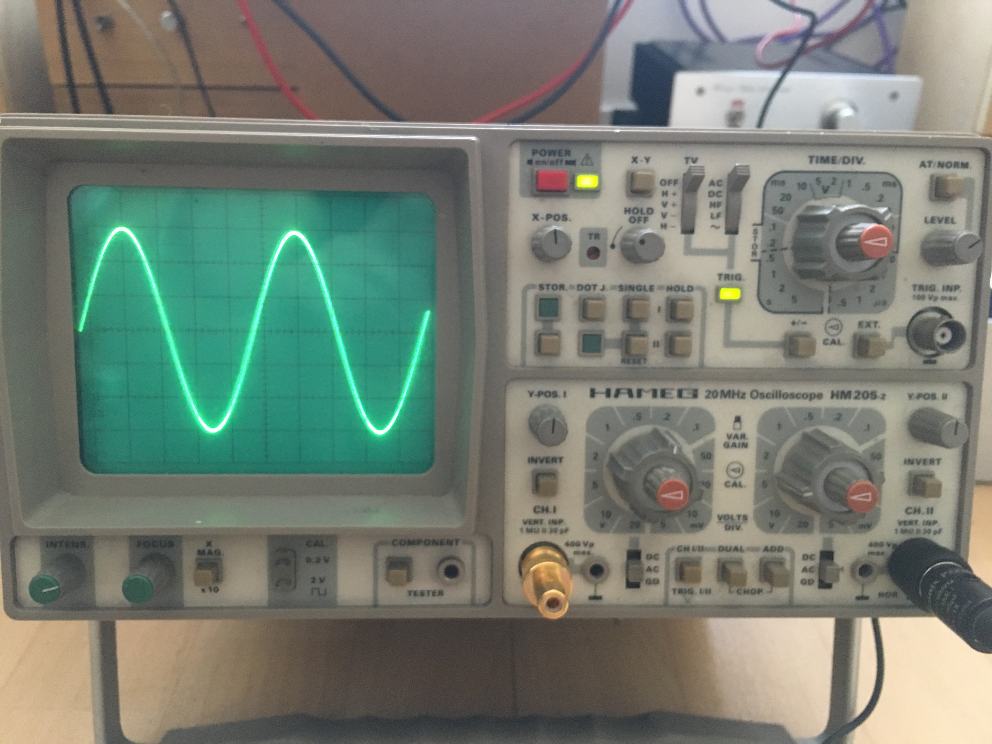
Ah! I thought you were trying to generate a squarewave test signal. OK, so that's fine as a sine wave test input.
Most amplifiers need only a small input voltage and so you need an attenuator (volume control) at the input. At 5 volts per division you have 30 volts pk/pk.
The scope image of the squarewave looks like some form of clipping but the amplitudes you mention don't make sense (20mv, 60mv etc).
Most amplifiers need only a small input voltage and so you need an attenuator (volume control) at the input. At 5 volts per division you have 30 volts pk/pk.
The scope image of the squarewave looks like some form of clipping but the amplitudes you mention don't make sense (20mv, 60mv etc).
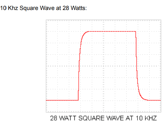
I'm not really understanding what you are trying to do here Both those images say 10kHz at 28 watts.
The first picture shows a typical squarewave from an amp that is well behaved and deliberately (in a good way) bandwidth limited perhaps by having a low pass filter at the input.
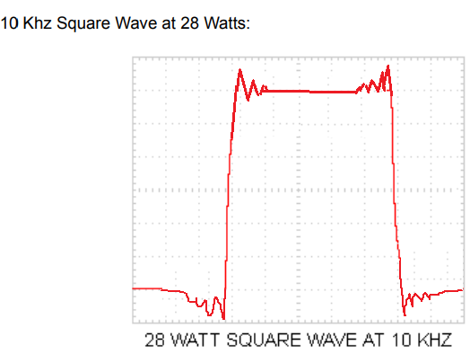
The second picture shows classic ringing and pre ringing such as you see from a typical CD player and its DAC/Filtering.
Gibbs phenomenon - Wikipedia
Both those images say 10kHz at 28 watts. The first picture shows a typical squarewave from an amp that is well behaved and deliberately (in a good way) bandwidth limited perhaps by having a low pass filter at the input.
The second picture shows classic ringing and pre ringing such as you see from a typical CD player and its DAC/Filtering.
Gibbs phenomenon - Wikipedia

 that looks much better. I suspected it could be the method of generating the signal that was the issue.
- Status
- This old topic is closed. If you want to reopen this topic, contact a moderator using the "Report Post" button.
- Home
- Design & Build
- Equipment & Tools
- Oscilloscope wave form