One of the limitations of the 3585B for audio work is the +30dBm (7V) max input range. Many of my power amps do rather more than that.
I've been working with either CRO probes (very accurate but a bit tedious to use) or a simple resistive divider (either low impedance on the DUT or else very inaccurate) for a while.
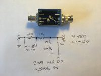
Anyway, today I figured I'd knock something more betterer up. I wanted to preserve the 1MΩ input impedance, so started with a straightforward resistive divider - 900KΩ and 111KΩ, which gives ÷10 when the 111KΩ is in parallel with the 1MΩ 3585B input impedance.
In reality I used 680KΩ in series with 220KΩ to give 900KΩ, and a 1MΩ, 470KΩ, and 120KΩ combination to give ~111KΩ.
That works well at DC, but by 100KHz I was down ~4.5dB. The 30pF input capacitance of the 3585B was really messing with it.
So I stuck a capacitor across the 680KΩ on the input - I used 10pF fixed in series with a 5-15pF trimmer, which was right on the money. I chucked the whole mess in a nice little Pomona box.
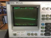
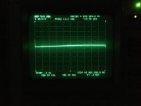
Anyway a picture is worth a thousand words. My 3dB bandwidth is 230KHz, and I'm within 0.2dB to 90KHz. I reckon that'll do for audio work.
I've been working with either CRO probes (very accurate but a bit tedious to use) or a simple resistive divider (either low impedance on the DUT or else very inaccurate) for a while.
Anyway, today I figured I'd knock something more betterer up. I wanted to preserve the 1MΩ input impedance, so started with a straightforward resistive divider - 900KΩ and 111KΩ, which gives ÷10 when the 111KΩ is in parallel with the 1MΩ 3585B input impedance.
In reality I used 680KΩ in series with 220KΩ to give 900KΩ, and a 1MΩ, 470KΩ, and 120KΩ combination to give ~111KΩ.
That works well at DC, but by 100KHz I was down ~4.5dB. The 30pF input capacitance of the 3585B was really messing with it.
So I stuck a capacitor across the 680KΩ on the input - I used 10pF fixed in series with a 5-15pF trimmer, which was right on the money. I chucked the whole mess in a nice little Pomona box.
Anyway a picture is worth a thousand words. My 3dB bandwidth is 230KHz, and I'm within 0.2dB to 90KHz. I reckon that'll do for audio work.
Attachments
I just saw your earlier thread - Playing with an HP3585B low frequency spectrum analyser
Have you been able to cross-check the amplitude accuracy - the spec sheet accuracy looks to be well under 1db for that span and dB/div.
Having vintage gear around can certainly be an advantage for audio, especially for cross-checking esoteric issues like output transformer resonances that can kick in beyond 100kHz where the bandwidth of many instruments can peter out. My only reference out to 1Meg was a HP3400A (so its a leap of faith that its somewhat still in cal out beyond 100kHz where my other meters get to), even though I could generate to that extent.
Last edited:
I used the analyser’s own tracking generator as a source to make that. When it self cal’s, that’s the source it uses, so if I connect the tracking generator direct to the 1MΩ input, I get a (very) flat line, as all I’m seeing is any errors that have crept in since last time it cals. I simply adjusted the tracking generator level to 0dBm.
So then when I insert the attenuator, I’m making a relative measurement. I think I’d trust it to within 0.1dB or so.
I have nothing at home to do an absolute cal beyond maybe 100KHz, which is where my HP3478A runs out of puff.
So then when I insert the attenuator, I’m making a relative measurement. I think I’d trust it to within 0.1dB or so.
I have nothing at home to do an absolute cal beyond maybe 100KHz, which is where my HP3478A runs out of puff.
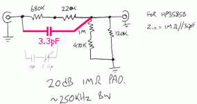
...I stuck a capacitor across the 680KΩ....
Strictly, the top leg cap should go across the whole 900k and be near 3.3pFd.
Your way has error above maybe 230kHz? I'm not sure of my 3-second analysis, but you found the same number.
"Correctly" compensated the bandwidth is "infinite" (or until other parasitics grow and bite you).
Attachments
me> my 3-second analysis
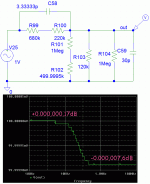
The Idiot Assistant does this stuff better. Your nearest standard value resistors are real close, but as long as too-many-digits are cheap I found one closer value (of impractical precision).
By playing with deep digits I found "dead flat" but that is boring and un-real. Here's a very very very very minor error. The jagginess of the step shows that SPICE is down to its last bead (real analog parts would be dead smooth).
Attachments
Yes, of course. I confess I connected the cap to the middle of the two resistors for no better reason than that it was something of a stretch otherwise.
Here's what I get with a couple of 10pF caps in series plus my trimmer, stretched all the way across between the two ends of the case.
I'm flat to within 0.3dB all the way to 40MHz, which is as far as my 3585B goes.
Next time I'm ordering parts I note that Mouser do 900K and 111K 0.1% resistors, so I'll buy a couple and do a proper job, and I'll even knock together a little PCB - can no doubt get it a fair bit flatter than it is with minimal effort.
Attachments
Last edited:
- Status
- This old topic is closed. If you want to reopen this topic, contact a moderator using the "Report Post" button.
- Home
- Design & Build
- Equipment & Tools
- A 250KHz BW 1MΩ 20dB pad for the 3585B