I recently purchased a Heathkit IM-18 VTVM . I did a thorough cleaning, visual exam, component check and calibration. The tubes have tested and passed. Cross tested performance against a Fluke 179 . -- Ohms and DC functions are very acceptable. However I am confounded by its inaccuracy in the lower ranges of AC signal testing.
Inputting AC from a Variac yields very accurate results in the higher ranges. For the lower 5v and 1.5v ranges, I input a 1kHz sine wave with a signal generator . The accuracy of readings below 5 volts are about 20% lower than the DMM. A larger 30% error discrepancy is seen on the 1.5v range. In other words, 650mV on the DMM is seen as 500mV on the VTVM.
Is such an error normal for this "service grade" meter??. Is this characteristic of old VTVMs? (I've never used one before) Or, is it a malfunction that can be repaired? Either way, this may be an opportunity for me to learn something.
I don't know if there is a role for a VTVM in my serious amateur electronics adventures, but its very high input impedance is attractive and, like me, it is 'vintage'. I guess I'll stick with my DMMs unless this is something that can be corrected/improved.
Thanks for your advice
attached schematic:
Attachments
It uses a simple vacuum tube rectifier for AC which will show some error for low AC voltages from its internal drop. I had one in the '70s and it was adequate for basic service but not for anything requiring precision. Then again the alternative was a Simpson which also had limitations.
It won't replace a decent dvm which can be pretty cheap today.
It won't replace a decent dvm which can be pretty cheap today.
... 650mV on the DMM is seen as 500mV on the VTVM....
Did you find calibration instructions? (Would be similar for most VTVMs.) Did you trim R5 AC Balance properly?
ALSO check/replace the main filter cap!! Especially if you are "checking" with line voltage (Variac). The VTVM will "read" with huge ripple in its power supply. But if the power ripple syncs/not-syncs with the signal frequency, AC readings will be erratic.
That aside: the 6AL5 vacuum diode has about 100mV uncertainty in its voltage drop. This form has two diodes so 200mV uncertainty. 650/500mV error sounds high, in my long-ago experience, but may be "normal". 50/100mV error would be real normal; the diode curve is very flat and drifty down there.
If you actually want to read small AC voltages you want an ACVM. Boonton, H-P. (A wrinkled black Boonton Ballentine will need significant restoration by now, the H-P would be a better bet.)
Or use TL072 as gain and precision rectifier to drive your Heath VTVM's DC input. With a well-seasoned 12AU7 (never turn it off) the Heath will have ~~10mV of zero drift and when calibrated and zeroed it will be good for better than 2% precision of DCV.
The other thing you can do: rectify the 6VAC to about 7VDC and regulate to 1.54V with a LM317, replace the rotten C-battery and holder on the Ohms function. Note that needle-meter Ohms can be good for many things a DVM won't well, or need added features.
Last edited:
Thanks for your very informative replies. You've confirmed my suspicions that the AC measurement discrepancy is characteristic of these 'unsophisticated' vintage VTVMs. The contrast between the ol' analog tube and digital world is apparent. Given these comments, I realize that my expectations for precise measurements using this Heathkit were a bit to high.
I am intrigued by the IC/transistor mods that PRR suggests though my knowledge base in electronics is lacking for the 'how-to" in this case. Has anyone performed such mods?
This VTVM problem presents an opportunity for hands-on learning . I will proceed to refurbish this instrument as I have found the values in several components out of tolerance. ... Might help/might not? If nothing else, it is good soldering practice and a way to gain some understanding of this circuitry.
Thanks, again, for giving me some insights.
Plain old VTVMs were unsophisticated at measurments at the fringe of their specs, but Heath also made AC VTVMs, like the IM-21:
AC Vacuum Tube Voltmeter IM-21 Equipment Heathkit Brand,
AC Vacuum Tube Voltmeter IM-21 Equipment Heathkit Brand,
A bit like steam engines, VTVMs are mostly good for entertainment value. The offset of the rectifier is going to make low voltage measurements inaccurate. Free DVMs from Harbor Freight work well for about a month, and then you go get another.
Here at DIYA there are many folks that love their sound systems with a library of vinyl or CDs. But even though my home has lots of space, I am not about to reserve a room for such things. The CDs are in a box in the basement and 400+ albums live on a thumb drive in the cars, on my phone, and a folder on each computer. As time goes by, the pressure from the wife increases to dispose of my old tapes and the amps I built 40, almost 50 years ago. Perhaps there is a museum that might want your VTVM, but do you have space for you own museum?
Here at DIYA there are many folks that love their sound systems with a library of vinyl or CDs. But even though my home has lots of space, I am not about to reserve a room for such things. The CDs are in a box in the basement and 400+ albums live on a thumb drive in the cars, on my phone, and a folder on each computer. As time goes by, the pressure from the wife increases to dispose of my old tapes and the amps I built 40, almost 50 years ago. Perhaps there is a museum that might want your VTVM, but do you have space for you own museum?
Last edited:
Don´t be unfair to this very reliable and precise *bench* meter., I realize that my expectations for precise measurements using this Heathkit were a bit to high.
All measurement scales are very accurate *except* very low AC measurements (your 1.5VAC scale) because, as said above,it uses a vacuum tube double diode.
And Hi Fi audio was not what the typical repairman found on his bench, but TVs, Radios, some Home Consoles (Radio + record player combination) , the odd PA amplifier (think Church, School or Supermarket use) and for all those it works fine.
To better measure low level RF and Audio signals, you added an "RF probe" or "Audio Probe" with a couple germanium diodes, way more sensitive than 6AL5:

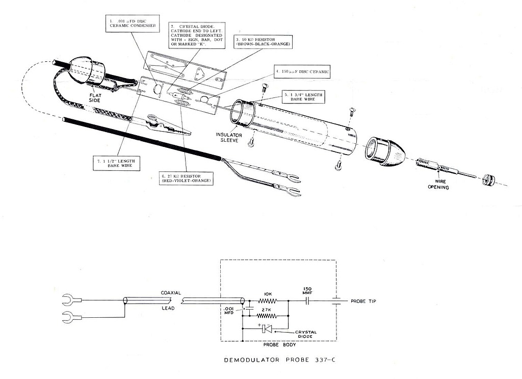
As you see, flat to 100MHz ... try that with *any* digital meter
")
And you and I are "old style guys", young people have no use for analog audio and very little use for Multimeters , just get straight into their Digital devices.
Each Era has its own techno stuff
Last edited:
...IC/transistor mods that PRR suggests though my knowledge base in electronics is lacking for the 'how-to"....
That C-cell (only used for Ohms) is always rotten. Soon after, the cell holder is all rot. Long-term the rot can spread to the rest of the guts. (I recall Heath at least put the cell in the bottom, so it only ate the case, unless it was flung in a box or on its back for an extended time...)
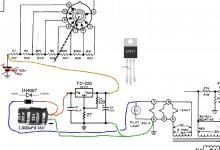
When LM317 was new, I realized it was a total fix. Heath's heater is 6.3V AC one side grounded. A half-wave rectifier is not ideal for a heavy load but this load is light (even on the 10r range). Probes short on 10r range, the heat in the LM317 will approach 1 Watt; otherwise much less. A naked TO220 will handle a Watt; not forever but for the time I would have 10r shorted. The suggested 120:27 resistors program for a 1.53V output, more or less, but whatever it is *can* be matched with the front panel OHMS trimmer (which has to handle a C-cell as it decays toward 1V).
The LM317 metal tab is "live", can not be bolted to the case. (I hear you can buy all-plastic ones now.) I just spread the legs to fit a scrap terminal strip and let the tab fly. C1 is not necessary if less than few inches of wire to the new main cap 1,000uFd (330uFd-2,200uFd). C2 may not be essential but it won't be clear "if" it is needed, so just do it. (1uFd-200uFd, whatever is at hand.)
Similar will work on other brands, but do due diligence. Some brands ground the other side of the battery which leads to a LM337.
Attachments
- Status
- This old topic is closed. If you want to reopen this topic, contact a moderator using the "Report Post" button.
- Home
- Design & Build
- Equipment & Tools
- VTVM accuracy for very low AC?