Yes of course, the AA2380 board have two channels !
The measurement show only one channel, but both give same results.
May measure the channel cross talk using L=1kHz and may a R=10Khz...

Hp
Frex, I do not have the AKM readings in mind, but are the SAR measurements better than the AKM?
Here is an example with the same generator and the AK5394A:
DIY Audio Analyzer with AK5397/AK5394A and AK4490
TNT,
The AA2380v1 board I tested (with the AAPSU01 board) is the standalone
part of the OSVA analyzer project.
Because the on-board CPLD is small (low LE count), it is only possible
to use internal SinC filter of the LTC2380-24 ADC.
Depending on the selected sampling rate, is vary from x8 to 32x
for always a real ADC rate of 1536 Msps.
The coming AA10M08 is a daughter board plugged on AA2380.
It will offer several connections and include much bigger FPGA that allow
use any filter type (IIR / RIF) and control a display GUI.
You can take a look on firsts page of the thread for more complete
information about project architecture.
HpW, good idea.
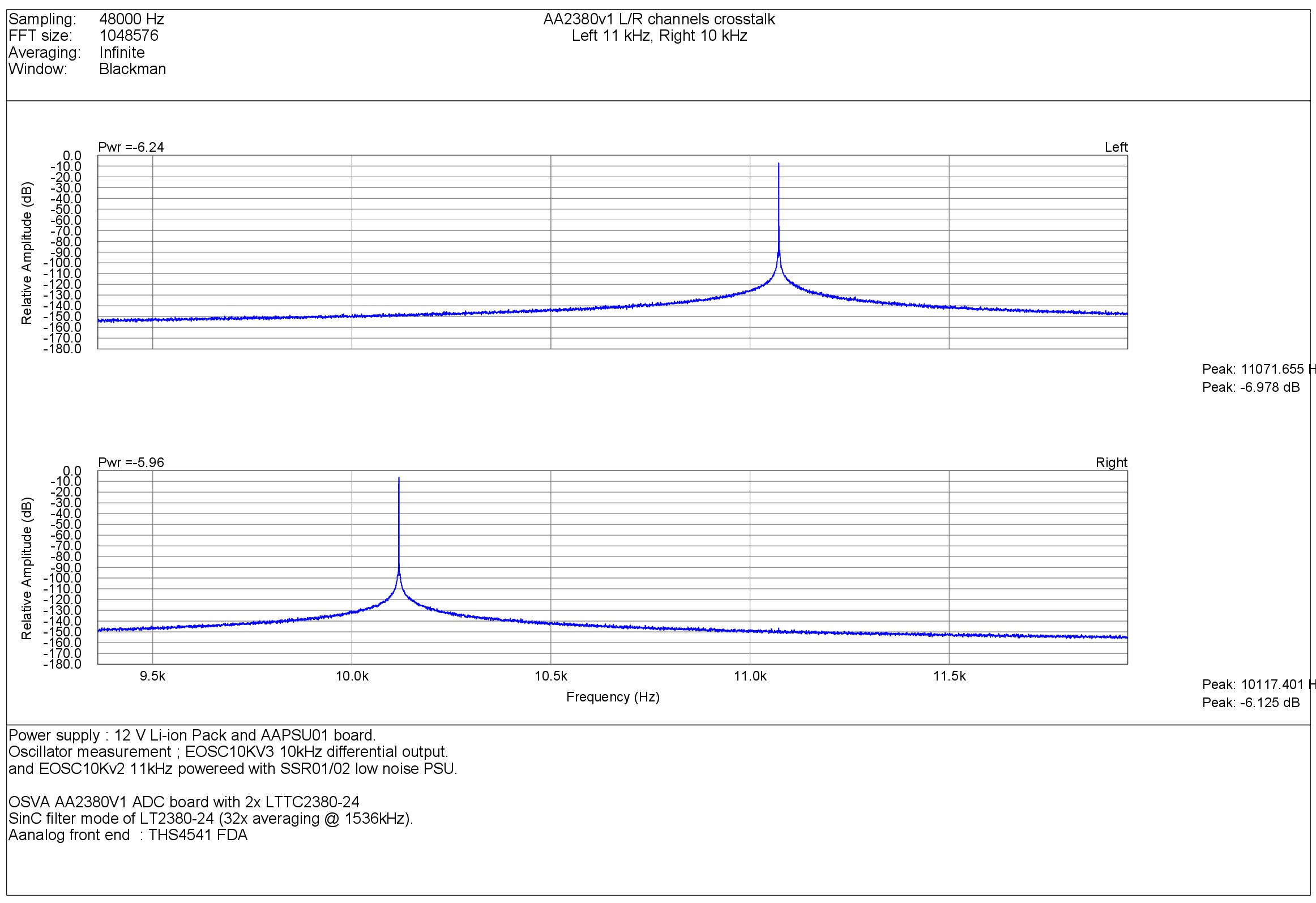
Below the FFT result of 2 sines 10kHz and 11kHz on both channels
to see cross-talk.That look fine...
AA2380V1 - LTC2380-24 ADC based channels cross-talk.
electron-ic,
I think you would wait a little for a finished product..)
Anyway, the project is open source and all files are available (or will be soon) on Github.
Frex
The AA2380v1 board I tested (with the AAPSU01 board) is the standalone
part of the OSVA analyzer project.
Because the on-board CPLD is small (low LE count), it is only possible
to use internal SinC filter of the LTC2380-24 ADC.
Depending on the selected sampling rate, is vary from x8 to 32x
for always a real ADC rate of 1536 Msps.
The coming AA10M08 is a daughter board plugged on AA2380.
It will offer several connections and include much bigger FPGA that allow
use any filter type (IIR / RIF) and control a display GUI.
You can take a look on firsts page of the thread for more complete
information about project architecture.
HpW, good idea.
Below the FFT result of 2 sines 10kHz and 11kHz on both channels
to see cross-talk.That look fine...
AA2380V1 - LTC2380-24 ADC based channels cross-talk.
electron-ic,
I think you would wait a little for a finished product..
)Anyway, the project is open source and all files are available (or will be soon) on Github.
Frex
Frex,
Awesome work (as usual) on this and thanks for making the design open source and hosting it on GitHub for collaboration! I was able to load the project into KiCad locally, and after adding the included symbol library successfully, view the schematic and board layout. It appears your local 3D models appear to be missing from the repo, if you upload those and change the references to be relative to the project directory, then everyone should be able to pull those into their local copies as well.
Do you have the AAPSU01 design files up on GitHub as well? I know the schematic covers all of the modules, but I didn't see a board layout for the PSU yet.
During design did you consider a specific enclosure for the finished build? Is it meant to slide into a card slot for a hammond case like some of your previous designs? I have a some experience with Fusion 360 and a CNC at home and would be interested in contributing an enclosure design based off of something from Hammond or Takachi if that would be useful.
Thanks again!
Greg
Hello,
ChrioN,
There is no latency at all. When the future AA10M08 digital daugther board
will be connected a to AA2380 board then it would be possible to use any filter type (FIR/RIF or nothing).
Gtose,
I must update the Github repository and add all missing files.
It's planed, but not done yet. I'll try to do it quiclky.
About the enclosure, i thinking to use the Hammond 1455T2201.
Everything should fit in.
Front and rear panels would be made in PCB to be already drilled wit a silkscreen
for an easy build and a nice looking. Anyway, for now there is lot of work
to be done before and nothing is freezed.
Regards.
Frex
AA2380V1 first THD mesurements with ADA4945-1
Hello,
I'm continuing to make some tests and measurements on the AA2380v1 ADC board.
The AA2380v1 circuit board has been designed to allow various FDA to be mounted.
I tried first the THS4541, very high bandwidth amplifier.
It work quite well (as my previous FFT screenshots show), but i wanted try also the FDA
i choose initially : the ADA4945-1 . One of it's main advantage is lower bias current, lower 1/f corner
and a wider supply voltage that allow some margin even near to ADC full scale.
(I made also some test with the OPA1632 FDA, but THD results are not as good).
For now, the ADA4945-1 is the better candidate, and it perform very well.
You can show a plot of what i obtain with -6 dB FS input level (5Vpp) 1kHz sine-wave
from my EOSC10Kv3 oscillator (direct connection, fully differential mode,
no filter, Fs= 48kHz (LTC2380-24 internal SinC filter average 32x - Fso 1536 kHz).
OSVA - AA2380v1 -6dBFS 1 kHz THD (diff input / ADA4945-1 buffer).
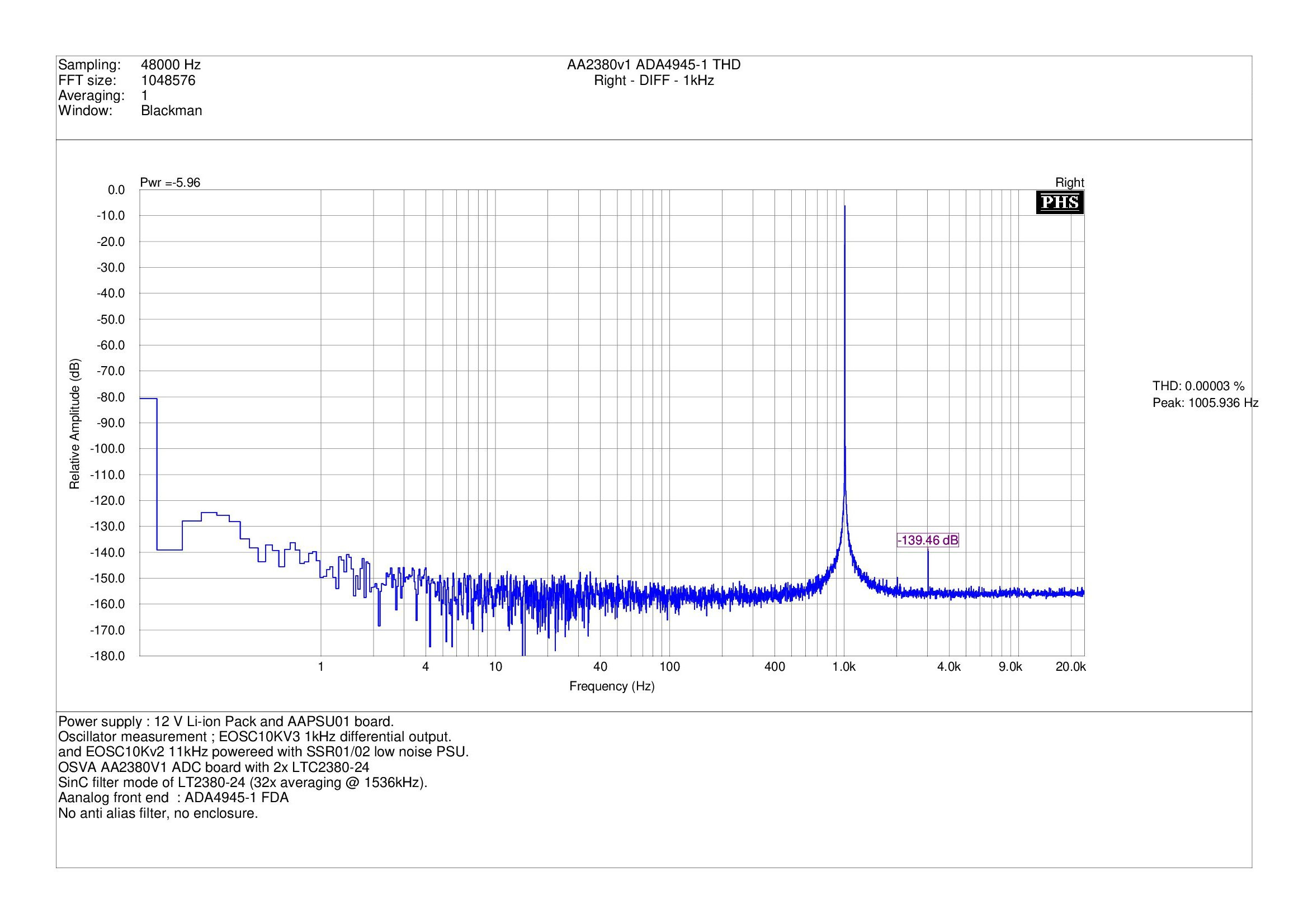
As we can see, even with no shielding (the PCB is just put on the desk), the FFT is very clean.
The highest harmonic show a level -133 dB down to carrier ! (0.000024%).
These results are promising.
Frex
Hello,
I'm continuing to make some tests and measurements on the AA2380v1 ADC board.
The AA2380v1 circuit board has been designed to allow various FDA to be mounted.
I tried first the THS4541, very high bandwidth amplifier.
It work quite well (as my previous FFT screenshots show), but i wanted try also the FDA
i choose initially : the ADA4945-1 . One of it's main advantage is lower bias current, lower 1/f corner
and a wider supply voltage that allow some margin even near to ADC full scale.
(I made also some test with the OPA1632 FDA, but THD results are not as good).
For now, the ADA4945-1 is the better candidate, and it perform very well.
You can show a plot of what i obtain with -6 dB FS input level (5Vpp) 1kHz sine-wave
from my EOSC10Kv3 oscillator (direct connection, fully differential mode,
no filter, Fs= 48kHz (LTC2380-24 internal SinC filter average 32x - Fso 1536 kHz).
OSVA - AA2380v1 -6dBFS 1 kHz THD (diff input / ADA4945-1 buffer).
As we can see, even with no shielding (the PCB is just put on the desk), the FFT is very clean.
The highest harmonic show a level -133 dB down to carrier ! (0.000024%).
These results are promising.
Frex
Hello,
Yes it work down to DC (input path is fully DC coupled).
The AA2380 CPLD doesn't include an HPF because it would require more logic cell,
but it use a DC calibration process to remove DC part by subtracting it (can be initiated at any time).
The daughter board AA10M08 will include much more math processing and of course a digital HPF.
And Merry Christmas to all too !
Frex
Thank you very much for the detailed explanation.
Yes I have seen, that its DC-coupled in the schematic. Personally I think, the potential of being capable to sample and process DC-signals would be a huge bonus, since all Delta-Sigma based Audio-ADCs (i.e. the ubiquitous soundcard solution) are definitely not DC-capable.
I am looking forward to follow your project progress. Take your time!
- Home
- Design & Build
- Equipment & Tools
- OSVA - Open source Versatile Analyzer