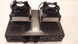
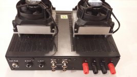
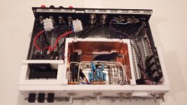
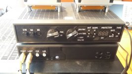
Finally finished my amp measurement adapter with fully balanced outputs. Balanced inputs/outputs are required for measuring bridged/digital amps, but eliminate ground loops in measuring regular amps too.
The adapter is designed to fit my https://www.diyaudio.com/forums/equ...adless-amplifier-measurement-workstation.html but will work with any soundcard - unbalanced stereo inputs are simple to turn into balanced mono input with improved performance https://www.diyaudio.com/forums/pc-...balanced-regular-soundcard-linux-results.html
All construction files (Fusion 360 sources, STLs) and details are available at GitHub - pavhofman/speaker-adapter: Adapter for measuring amplifier outputs, regular GPL licence.
Attachments
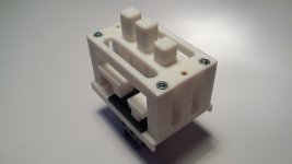
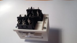
The 3D-printed switch parts got finally rendered on thingiverse Push Buttons Switch for 2 Resistors Parallel Combination by pavhofman - Thingiverse
Thanks for this @phofman!
If you don't mind, I have a couple of questions about the schematic:
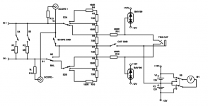
1. What is the purpose of the resistors at the outputs? The 1K resistors at the scopes/BNC connectors and the 680 ohm resistors on the main TRS output?
2. This may be more than is easy to describe here (there is likely a huge amount of background knowledge I'm missing) but what is the purpose of the +/- 12V battery/BAV199 diode circuit? I'm assuming some sort of protection function - how does this work?
Thanks!
If you don't mind, I have a couple of questions about the schematic:
1. What is the purpose of the resistors at the outputs? The 1K resistors at the scopes/BNC connectors and the 680 ohm resistors on the main TRS output?
2. This may be more than is easy to describe here (there is likely a huge amount of background knowledge I'm missing) but what is the purpose of the +/- 12V battery/BAV199 diode circuit? I'm assuming some sort of protection function - how does this work?
Thanks!
The diodes with batteries protect the soundcard input from overvoltage. Juli@ input range on balanced inputs is +/-10V against ground each line (hot, cold). That is why 12V batteries. I use small A23s with low capacity (high internal resistance, a pair in parallel for each branch is used to increase the capacity). Large current in case of large overvoltage would make the battery protection ineffective, that is why the serial resistors. Juli@'s input impedance is 10k, I could not use much higher than those 680R.
Since the protection capability of small A23s is not high, the added voltmeter allows to check their status before measuring. The measurement current is about 10mA, already slightly loading the batteries. The protection could certainly be made more robust.
BAV199 has very low leakage, not distorting linearity of the measurement significantly.
Serial resistors in scope lines - just short-circuit protection.
Last edited: