Demian is correct, IME you will not get -120dB from either the EMU or Scarlet 2i2 either. To repeat one more time, the distortion magnifier (bridge null) principle eliminates the need for an attenuator or a super sound card. Page 10-15, 10-16 here http://www.analog.com/media/en/technical-documentation/application-notes/5866763300941AN245.pdf
Last edited:

...The M33078 input buffer amplifiers have THD specs of 0.002% and a supply voltage range from 10V to 36V. Thus with 5V supply, the input amplifiers are supplied significantly below the minimum supply voltage. That they still function may be because they are particularly screened. ...
The TI sheet shows +/-5V.
The ST sheet shows +/-2.5V, and figure 2 shows it biases-up by 2.5V total (+/-1.25V). Nothing on the simplified schematic given by ST disagrees with it working "fine" with just a 5V supply.
In the +/-15V world, the M33078 is said by a few designers to be "sweet", and is found in some high-class studio gear.
Agree it is very possibly a cost-constrained product and there may be many places that "could be better". But also note the G5 is specifically aimed as a headphone solution, not a measurement tool. And the price reflects that. (It is over-priced for what it is to improve sales aura.)
Demian is correct, IME you will not get -120dB from either the EMU or Scarlet 2i2 either. To repeat one more time, the distortion magnifier (bridge null) principle eliminates the need for an attenuator or a super sound card. Page 10-15, 10-16 here http://www.analog.com/media/en/technical-documentation/application-notes/5866763300941AN245.pdf
Dear Scott, This document is just splendid. I never got into high performance measuring circuits as my line of business turned into power conversion and regulation with some more simple protocol analyzers and control/test systems. I wondered how to do an ultra low THD test and this document gives me the answer: balance out the test signal and amplify the residual. Further, it tells me how an instrumentation amplifier is constructed. Great! 140dB measurements already back in the days when I started in the lab and we bought components from AD and BB when we just didn't want any problems. You and Walt made sure the components were of highest standards.
No, I do not expect the SBX G5 ever to do 120dB, even when modified. Perhaps some 105dB-110dB if I do a good job. The present 70dB I find pathetic.
120dB would be great, 130dB splendid and 140dB unbelievable. I will try out the balancing principle described in the document. It is so logical, rather simple and very high performance. That will leave me with the challenge of making a 140dB sine-wave oscillator. With modern OP-AMPs and using the Wien-bridge coupling the oscillator part is rather simple, but the AGC is not trivial as most variable resistance compounds show non-linearity effects and causes the THD to raise. Would you know of a variable resistance material that is highly linear?
Scott, many thanks for your valuable comment. It's all about finding the guy/girl who really knows.
FF
Last edited:
The TI sheet shows +/-5V. The ST sheet shows +/-2.5V, and figure 2 shows it biases-up by 2.5V total (+/-1.25V). Nothing on the simplified schematic given by ST disagrees with it working "fine" with just a 5V supply. In the +/-15V world, the M33078 is said by a few designers to be "sweet", and is found in some high-class studio gear. Agree it is very possibly a cost-constrained product and there may be many places that "could be better". But also note the G5 is specifically aimed as a headphone solution, not a measurement tool. And the price reflects that. (It is over-priced for what it is to improve sales aura.)
PRR, you are right I may have been naiv. It is called a sound-card for "gaming".
Finding my best magnifying glass I could see they are M33078 from TI in the SBX G5. That may be a further "mistake" if the designers assumed ST to be the source and it was produced with TI as source. I assume second source ICs with the same type-name to be produced to the same specifications but with individual wafer layouts such that a TI may perform differently than an ST outside of specifications.
I believe I found an M33078 in a "Musical Fidelity" unit. It is not that I believe it to be poor as long as it is given the right supply voltages to perform under.
As I stated in a previous posting, it is the mix of good components (DAC/ADC/TPA6120) with perhaps slightly less suited amplifier chips, and solid under-voltage supply that leaves the impression of poor balancing by the designers. And on top, a performance claimed by the PR-guys that is only based on the DAC/ADC.
Thanks for your comment.
FF
Last edited:
I found and bought something called "Vactrols". Photocouplers with an LDR output element. Used below 200mV rms, the linearity should be quite good (0.02% THD). As they only need to be a small part of the gain setting network, this should do the job.
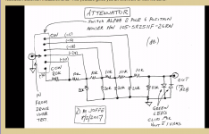
I like your switchable attenuator. Although I did have one suggestion. Maybe it's a good idea to include 2 pairs of 2 regular diodes as well, with each pair oriented the same as each green leds. This will prevent the case of major over load if one or both of the leds were to fail.I've updated this web-page to include a pdf file that describes how to build a switchable attenuator to use with a sound card. It enables using a soundcard to measure a power amp:
1 kHz Oscillator
Guys, I just want to use ARTA to measure distortion products H2 and H3 out my amps and preamps. I think off the shelf for me is plenty good or how precision does this need to be?
Cheers and thanks for posting the YouTube video.
Greg
Cheers and thanks for posting the YouTube video.
Greg
Maybe it's a good idea to include 2 pairs of 2 regular diodes as well, with each pair oriented the same as each green leds. This will prevent the case of major over load if one or both of the leds were to fail.
Why? The LEDs are very well protected and unlikely to fail.
In the worst case scenario, a misguided user sets the selector switch to the top ("-6") position and applies a ±100 volt square wave (!!) to the input. Thanks to the 10K series resistor, the LED current is limited to ten milliamperes, well within its safe operating area.
Schematic below.
_
Attachments
Guys, I just want to use ARTA to measure distortion products H2 and H3 out my amps and preamps. I think off the shelf for me is plenty good or how precision does this need to be?...
How dirty are your preamps??
Single tube boosters with 0.5% THD, any non-defective sound card is ample.
Low-low-low-THD many-transistor preamps may challenge the best sound cards.
Question. If I am measuring a loopback distortion of 0.007% and I then hook up my amplifier and measure 0.015% what is the distortion of my amplifier?
It's more complex than that really. As a basis your floor should be around 10 dB or more below what you intend to measure. However even with 10 dB you can get audio d and subtraction depending on the phase relationship of the harmonics. 20 dB would be a better difference between test and residual.
No, sorry you can't just subtract the .007 from the .015. Unfortunately it doesn't work that way.
No, sorry you can't just subtract the .007 from the .015. Unfortunately it doesn't work that way.
So how do I measure it. Are you suggesting that I take down the amplitude of each harmonic while hooked up in loopback. Then once I measure the DUT I measure and subtract the difference between each harmonic. Then caculated the final THD value?It's more complex than that really. As a basis your floor should be around 10 dB or more below what you intend to measure. However even with 10 dB you can get audio d and subtraction depending on the phase relationship of the harmonics. 20 dB would be a better difference between test and residual.
No, sorry you can't just subtract the .007 from the .015. Unfortunately it doesn't work that way.
No I wish it were that simple. All you can do is check the difference between loopback and measured distortion. If the measured distortion at each harmonic is 10 dB more than the loopback then you can probably trust the number. If not you are at the limits of your measurement for real accuracy. In some circles this would be heresy, but really at .015% distortion is not a real issue with significant aural effect.
Use that number - 0,015%. But in reality, it can be somewhere between 0,015 and 0,007%. To be sure you have to improve something in your measuring system - use a little better soundcard (brute-force way), use better cables (shielding) or totally another measure technic.Question. If I am measuring a loopback distortion of 0.007% and I then hook up my amplifier and measure 0.015% what is the distortion of my amplifier?
I have a quick question for people using EMU devices, I have the 0202 but the
drivers are beta (probably from XP time frame) claimed to work in Win7. They
load in Win 10 but if people know if they work or not then I won't waste time trying
it out. I read that in Win10 devices should use WDM and be controlled from within
Win 10 Setup, but I'm getting an EMU setup tool to change sample rate for example.
I've dabbled with ARTA for many years but plan to now make it my primary tool.
I usually use LAUD on old Win 98 hardware, lol but it is not portable.
I have both a tracker pre and an 0404 USB working in Win 10 with the drivers. The 1212m and 1616m need some magic tweaks in the driver setup to work but its out there. I posted a link in the past.
They I do that is tp apply a most accurate sine wave at 100, 1000, 10000 Hz and measure the harmonics. My FPGA-System can calculate the THD(N) value automatically from that within a given range.
The measurement is done for serval input levels. This makes it possible to distinguish the impact of noise being introduced by the wave generator and the measurements. E.h. fpr very low input levels you will see more harmonics and from a certain point on this stay relatively constant.
The measurement is done for serval input levels. This makes it possible to distinguish the impact of noise being introduced by the wave generator and the measurements. E.h. fpr very low input levels you will see more harmonics and from a certain point on this stay relatively constant.
I have a naive question. I really like the look of Dan Joffe's attenuator. My question is -- is that level of precision needed, or can a simple variable resistor in series with a fixed resistor (which is where you would take the output) accomplish the same thing. Is the goal simply to reduce the level sufficiently to protect the external sound card? Of course, you could still put the LEDs in parallel with the fixed resistor just in case. I sense that I am missing something.
- Home
- Design & Build
- Equipment & Tools
- Distortion Measurement with Soundcard and ARTA software