Hi and Happy New Year ")
I have the unit mentioned above but I have some troubles There is no output from the RF out and some probs with the sweep out. Even though I have a signal, it isnt the common triangular one . Right now I am tracing the voltages starting from the PSU. Nevertheless the schematic or service manual would be nice to have. At least the operating manual..There is one similar unit RE104. Maybe there are some documents from this unit?
Thanks a lot in advance!!
Have fun
Philipp
I have the unit mentioned above but I have some troubles
There is no output from the RF out and some probs with the sweep out. Even though I have a signal, it isnt the common triangular one . Right now I am tracing the voltages starting from the PSU. Nevertheless the schematic or service manual would be nice to have. At least the operating manual..There is one similar unit RE104. Maybe there are some documents from this unit?Thanks a lot in advance!!
Have fun
Philipp
Hi Charles,
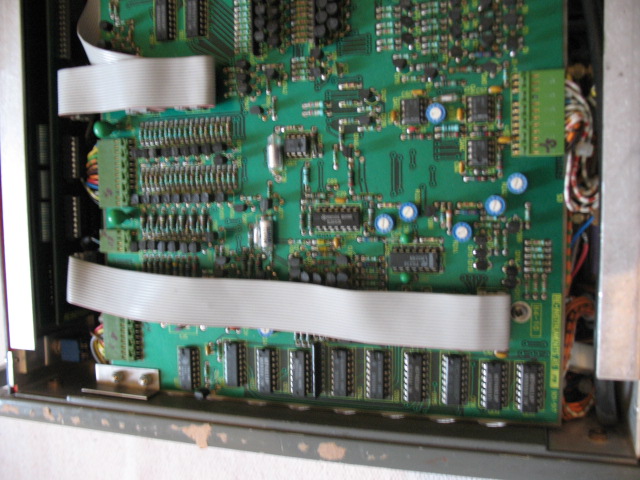
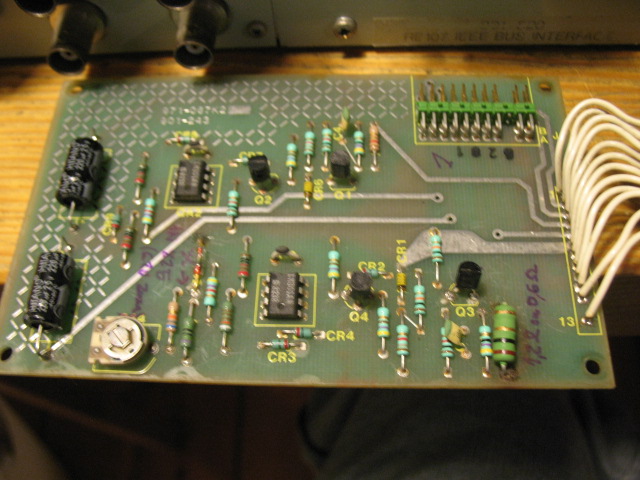
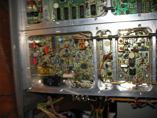
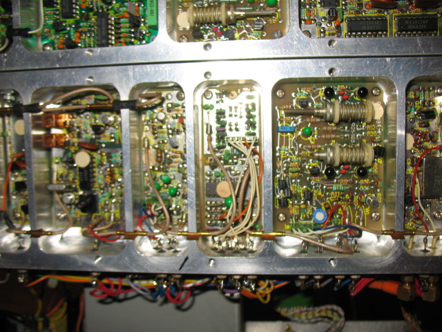
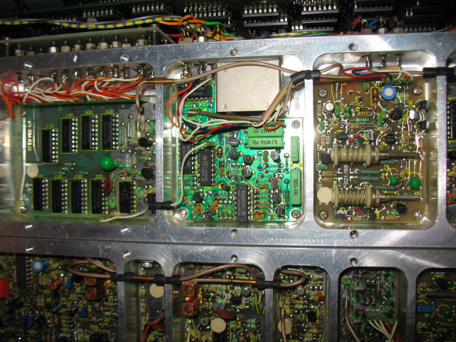
actually I havent tested it yet. I have troubles with the variable voltage regulators LM317T/LM337T. I think that these parts provide the +- 35VDC voltage. Because of that I wont get a RF signal. Nevertheless I will test if there is a signal going into the attenuator, because the output amp is feeded by +- 12VDC.
Here are some photos:
Cheers,
Philipp
Hi Charles,
there are some voltages missing, especially the ones generated by the variable voltage regulators LM337T/LM317T.
I may feed a signal from my R&S into the attenuator and check the output.
Cheers
Philipp
Photos are avaiable here:
Galerie: RE107 - abload.de
there are some voltages missing, especially the ones generated by the variable voltage regulators LM337T/LM317T.
I may feed a signal from my R&S into the attenuator and check the output.
Cheers
Philipp
Photos are avaiable here:
Galerie: RE107 - abload.de
Philippe,
Of course to get the unit working again you are going to have to supply (or fix) the "missing" voltages. My 104 works from + and - 12 Volts for the analog and +5 for the digital sections. The 35 volts you mention in your postings seems high. Input to the regulators from the rectifier/filter section? I have some radiometer equipment and have never had a problem with it - but then...
Charles
Charles
HI Charles,
yes, the positive and negative var. voltage regulator are attached to the psu by a pin connection. The output of the regulators feeds some parts of the unit. Further there are two fixed 5VDC regulators attached to the backside and I get +- 12VDC from the psu. Nevertheless the two var. regulators seems to make some trouble. Without a schematic or sth like that it is very difficult. Right now I am going to find some similarities with the schematic of the RE 101.
Philipp
Concerning the 35VDC, you will find this unregulated voltage in the RE101 PSU also. The schematic of the 101 is equal to the one of the 107 except that the 107 has two more regulators. I ve ordered them because the old ones seem to be defective. The PSU of the 104 should be almost equal to the one of the 107. Comparing the frontview these units are really similar. Actually the same functions except that the 107 has a pilot out at 98MHz, FM+AM and AM Stereo.
Philipp
Philipp
The 104 power supply has two 5V IC regulators and a bipolar 12V supply made from discrete parts. It is a tracking regulator with only one 12V adjust pot.
Are the "defective" regulators putting out some voltage; or "burnt out". If so, I'd suggest mounting the new ones off the board somehow so you can monitor the output current - may be a short "downstream" (like a bad tantalum bypass cap)
Charles
Are the "defective" regulators putting out some voltage; or "burnt out". If so, I'd suggest mounting the new ones off the board somehow so you can monitor the output current - may be a short "downstream" (like a bad tantalum bypass cap)
Charles
Hi Charles,
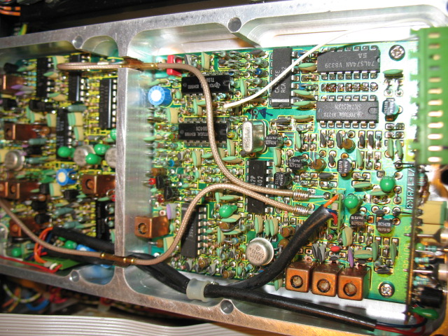
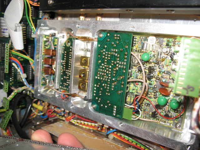
thanks for the info. I will check them today. Attached is a pic of the 2 regulators I am talking about. Further the +-12VDC are generated as you have said..
Here is the 12VDC pot:
and here the ones for the variable voltage:
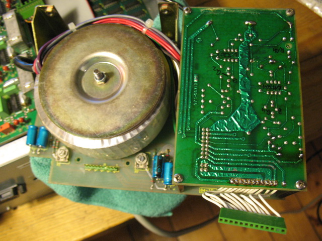
Additionally I ve found a source to get the manual + schematics. The bad info is that I will have to pay 74 Euro plus shipping
Philipp
thanks for the info. I will check them today. Attached is a pic of the 2 regulators I am talking about. Further the +-12VDC are generated as you have said..
Here is the 12VDC pot:
and here the ones for the variable voltage:
Additionally I ve found a source to get the manual + schematics. The bad info is that I will have to pay 74 Euro plus shipping
Philipp
As far as I understand it the unit has a pilot input on the rear. In connection with the spot frequency you may provide stereo S/N measurements whereas the spot frequency oscillator provides a very low noise signal for the S/N measurments.
To conclude there is no integrated stereo generator..
To conclude there is no integrated stereo generator..
- Status
- This old topic is closed. If you want to reopen this topic, contact a moderator using the "Report Post" button.
- Home
- Design & Build
- Equipment & Tools
- Radiometer RE 107 manual needed..