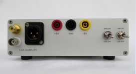
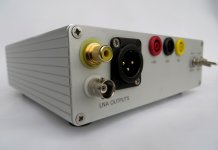
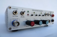
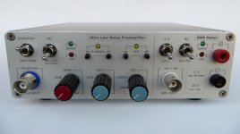
Ultra Low Noise Preamp & RMS Meter
Gain: 40, 60, 80 dB
Bandwidth:
-3dB: 5Hz - 1.5MHz, gain 80dB
-0.5dB: 10Hz - 1MHz, gain 80dB
Filters:Sallen Key, Order:2, Linear Phase 0.5°
(between butterworth and linear phase 0.5)
HIGH PASS: 20Hz, 1kHz
LOW PASS: 20kHz, 100kHz
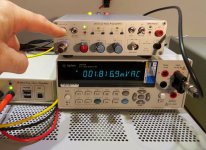
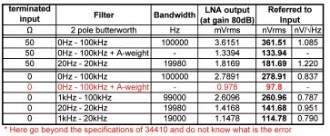
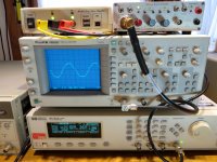
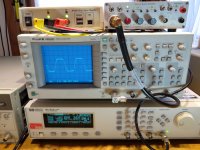
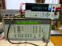
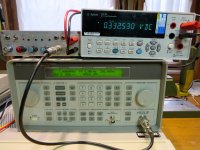
RMS noise: 361.51 nVrms (Referred To Input)
50ohms plug in LNA Input, Filters: 0Hz - 100kHz, Gain: 80dB
First, excuse me for my bad English. I use the Google Translate and technical knowledge of English.
It's my implementation for low noise measurement preamp and RMS meter which I has been made for personal use. Materials which I used for the project are:
Denis Colin Ultra low Noise Preamp in AudioXpress
http://www.mh-audio.nl/Articles\LowNoisePreAmp.pdf
10Hz..100kHz LNA // 1MHz RMS-DC converter by Frex
http://www.diyaudio.com/forums/equi...se-10hz-100khz-lna-1mhz-rms-dc-converter.html
Thanks to Frex for his ideas and his support about the RMS meter.
Application notes from Linear Technology
http://cds.linear.com/docs/en/application-note/an106f.pdf
http://cds.linear.com/docs/en/application-note/an83f.pdf
http://cds.linear.com/docs/en/application-note/an94f.pdf
All 100nF bypass capacitors in power supplies for the chips are PPS (Panasonic), 10nF are NP0, others - Wima. No X7R for their piezo effect.
Where necessary I have used low-noise and/or accurate resistors of WELWIN RC55 series, 0.1%, 15ppm. Also Czech TR163, TR192, TR161.
Parameters of the frequency response (10Hz - 1MHz at-0.5dB) at high frequencies are low signals. That is valid for small signals. The formula is FPBW (MHz) = Slew Rate / 2πVp. For example, for AD797 in 10Vpp and Slew Rate = 20V/μs I FPBW = 20/2 * 3.14 * 5 = ~ 640kHz.
One note about comparators measuring clipping. Original LM393N (National Semiconductor) did not deal at 1MHz. It required much higher levels of the input at this frequency in order to react. I tried 3-4 analogues from other manufacturers. Succeeded only BA393 (BA10393) of ROHM. Works great at 1MHz.
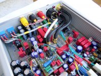
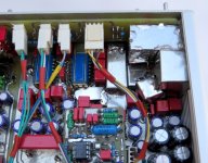
Once the PCB was ready, then I decided to add A-weight filter. So I forced some obfuscation in height. The filter is put on an extra PCB over main board.
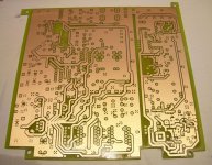
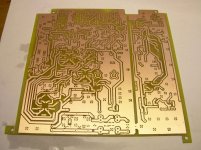
This is schematic and PCB board:
Gain: 40, 60, 80 dB
Bandwidth:
-3dB: 5Hz - 1.5MHz, gain 80dB
-0.5dB: 10Hz - 1MHz, gain 80dB
Filters:Sallen Key, Order:2, Linear Phase 0.5°
(between butterworth and linear phase 0.5)
HIGH PASS: 20Hz, 1kHz
LOW PASS: 20kHz, 100kHz
RMS noise: 361.51 nVrms (Referred To Input)
50ohms plug in LNA Input, Filters: 0Hz - 100kHz, Gain: 80dB
First, excuse me for my bad English. I use the Google Translate and technical knowledge of English.
It's my implementation for low noise measurement preamp and RMS meter which I has been made for personal use. Materials which I used for the project are:
Denis Colin Ultra low Noise Preamp in AudioXpress
http://www.mh-audio.nl/Articles\LowNoisePreAmp.pdf
10Hz..100kHz LNA // 1MHz RMS-DC converter by Frex
http://www.diyaudio.com/forums/equi...se-10hz-100khz-lna-1mhz-rms-dc-converter.html
Thanks to Frex for his ideas and his support about the RMS meter.
Application notes from Linear Technology
http://cds.linear.com/docs/en/application-note/an106f.pdf
http://cds.linear.com/docs/en/application-note/an83f.pdf
http://cds.linear.com/docs/en/application-note/an94f.pdf
All 100nF bypass capacitors in power supplies for the chips are PPS (Panasonic), 10nF are NP0, others - Wima. No X7R for their piezo effect.
Where necessary I have used low-noise and/or accurate resistors of WELWIN RC55 series, 0.1%, 15ppm. Also Czech TR163, TR192, TR161.
Parameters of the frequency response (10Hz - 1MHz at-0.5dB) at high frequencies are low signals. That is valid for small signals. The formula is FPBW (MHz) = Slew Rate / 2πVp. For example, for AD797 in 10Vpp and Slew Rate = 20V/μs I FPBW = 20/2 * 3.14 * 5 = ~ 640kHz.
One note about comparators measuring clipping. Original LM393N (National Semiconductor) did not deal at 1MHz. It required much higher levels of the input at this frequency in order to react. I tried 3-4 analogues from other manufacturers. Succeeded only BA393 (BA10393) of ROHM. Works great at 1MHz.
Once the PCB was ready, then I decided to add A-weight filter. So I forced some obfuscation in height. The filter is put on an extra PCB over main board.
This is schematic and PCB board:
Attachments
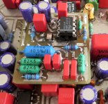
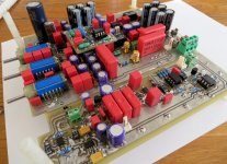
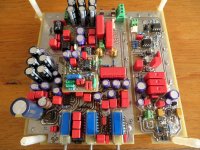
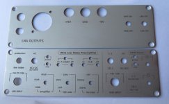
PCB
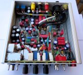
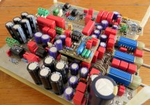
The PCB is double-layered. I've done at home with POSITIV20, tnen FeCl3, etc. The two layers are matched precisely with passers over transparency films. There are 775 holes of which 178 are vias. It's all drilled by hand with a nice machine PROXXON stand . Through holes drilled with 0.59 mm immersed exposed LAN wire (enter tightly in this hole), fold in about 2 mm on both sides and solder . For all these binders board seems rude. Metallization of passage in homeconditions is not only time-consuming and complicated, and with unclear quality. Wire is 100% secure.


When wiring am guided by the optimal placement of the elements in order to at least noise, possible short pats, many vias, additional shielding of sensitive noise units. No beauty. The beauty is at least, what I was looking for. Elements are deployed in various angles. Almost all standard resistors are mounted as SMD or semi SMD. After placing the components, I has been used LACQUER PLASTIK 70 to protect PCB from moisture, dirt, etc.


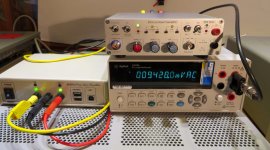
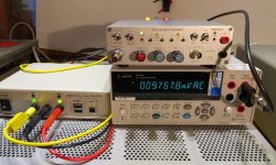
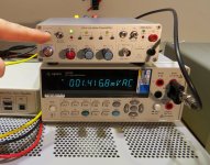
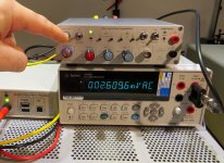
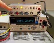
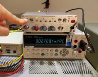
LNA noise measurement with Agilent 34410A:


LNA noise measurement with Multi-Instruments
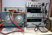
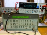
Some measurements with Multi-Instruments of Virtins and Emu-tracker PRE (ASIO). The initial calibration is made with an external generator (HP3325B) and Agilent 34410A (TrueRMS). Metering is done in the following settings: Sample 192kHz, 24bits, FFT 65536, Average 10. The vertical scale is in dBV. Received lower values for RMS: 332nVrms (50ohms input, 0-100kHz). I do not accept them many correct. I believe much more of measurements with 34410A for different frequency bands. I have photographed noise at protected input to see the noise of the 499 ohm input serial resistor.


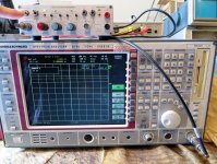
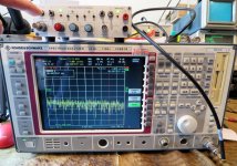
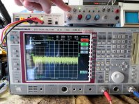
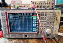
LNA measurement with Spectrum Alalyzer
Here are some measurements with a spectrum analyzer, which I did with friend. I do not know how far are correct b.p. that is my first work with Analyzer, a miracle and I do not know if they need any calibrations or normalization before measurement . The results are similar (slightly reduced ) . Analyzer has a built- RMS detector, which measures directly RMS at specified bandwidth . The result at RBW 100kHz is RMS average = 1.816mV. Since the output of the LNA have 50 ohm series resistor and it along with 50 ohm input of analyzer formed divider of 2. Therefore the real value of output of the preamplifier is 3.632mVrms. Referred to input at 80dB gain : 363nVrms.

When measuring the Noise Power Density I get 4.007μV / √ Hz. Multiplied by 2 for the output divider: 8.014μV / √ Hz. This referred to the input and 100kHz bandwidth: 270nVrms. For me there is something not very correctly. Value is lowered. And I do not know where exactly this bandwidth of 100kHz, where the measurement becomes.


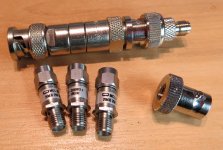
I could not measured the frequency response at low frequencies. This analyzer want any special settings and calibrations in a mixers and tracking generator to run correctly under 3kHz. All I can do to make it work from 100Hz on. The tracking generator level is -74dBm (6 dB lower) for divider 2 at the LNA output and analyzer Input. At the input LNA I have a 50 ohm feed through terminator.

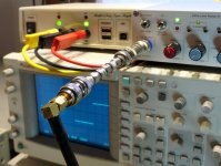
STEP RESPONSE at: 10kHz, 100kHz, 500kHz, 1MHz
At the input of LNA I put 500mVpp signal from generator reduced by attenuators 1,000 times. This signal is amplified 80dB (10000 times), and is supplied to the oscilloscope. Not exactly 1000 because of the accumulated error of the three attenuator and 50 ohm terminator. But this is not important, because examine only the waveform.


RMS Meter
Finally measurements with RMS meter. You have nothing to write. This is the old version of Frex's RMS meter. I decided that it was better for me. I do not need Logarithmic AC voltmeter. For me 34410A at low frequencies has higher accuracy and it measure down to 1mVrms. But just to 300kHz, and there is a big error. To 100kHz is OK. I made this RMS meter, because it works to 1MHz with relatively good accuracy (1% - 500kHz, 5% - 1MHz). The photos are in DC, 100kHz, 500kHz and 1MHz.


END
To end I would like to say that this preamp may be used not only for measuring the very small noise levels. It can be used as a plug-in oscilloscope for testing of small signals to 1MHz. In addition, It's an excellent plug-in for a good sound card to obtain a spectrum analyzer with extremely low noise.
If there are questions that I can answer - ask.
The PCB is double-layered. I've done at home with POSITIV20, tnen FeCl3, etc. The two layers are matched precisely with passers over transparency films. There are 775 holes of which 178 are vias. It's all drilled by hand with a nice machine PROXXON stand . Through holes drilled with 0.59 mm immersed exposed LAN wire (enter tightly in this hole), fold in about 2 mm on both sides and solder . For all these binders board seems rude. Metallization of passage in homeconditions is not only time-consuming and complicated, and with unclear quality. Wire is 100% secure.
When wiring am guided by the optimal placement of the elements in order to at least noise, possible short pats, many vias, additional shielding of sensitive noise units. No beauty. The beauty is at least, what I was looking for. Elements are deployed in various angles. Almost all standard resistors are mounted as SMD or semi SMD. After placing the components, I has been used LACQUER PLASTIK 70 to protect PCB from moisture, dirt, etc.
LNA noise measurement with Agilent 34410A:
LNA noise measurement with Multi-Instruments
Some measurements with Multi-Instruments of Virtins and Emu-tracker PRE (ASIO). The initial calibration is made with an external generator (HP3325B) and Agilent 34410A (TrueRMS). Metering is done in the following settings: Sample 192kHz, 24bits, FFT 65536, Average 10. The vertical scale is in dBV. Received lower values for RMS: 332nVrms (50ohms input, 0-100kHz). I do not accept them many correct. I believe much more of measurements with 34410A for different frequency bands. I have photographed noise at protected input to see the noise of the 499 ohm input serial resistor.
LNA measurement with Spectrum Alalyzer
Here are some measurements with a spectrum analyzer, which I did with friend. I do not know how far are correct b.p. that is my first work with Analyzer, a miracle and I do not know if they need any calibrations or normalization before measurement . The results are similar (slightly reduced ) . Analyzer has a built- RMS detector, which measures directly RMS at specified bandwidth . The result at RBW 100kHz is RMS average = 1.816mV. Since the output of the LNA have 50 ohm series resistor and it along with 50 ohm input of analyzer formed divider of 2. Therefore the real value of output of the preamplifier is 3.632mVrms. Referred to input at 80dB gain : 363nVrms.
When measuring the Noise Power Density I get 4.007μV / √ Hz. Multiplied by 2 for the output divider: 8.014μV / √ Hz. This referred to the input and 100kHz bandwidth: 270nVrms. For me there is something not very correctly. Value is lowered. And I do not know where exactly this bandwidth of 100kHz, where the measurement becomes.
I could not measured the frequency response at low frequencies. This analyzer want any special settings and calibrations in a mixers and tracking generator to run correctly under 3kHz. All I can do to make it work from 100Hz on. The tracking generator level is -74dBm (6 dB lower) for divider 2 at the LNA output and analyzer Input. At the input LNA I have a 50 ohm feed through terminator.
STEP RESPONSE at: 10kHz, 100kHz, 500kHz, 1MHz
At the input of LNA I put 500mVpp signal from generator reduced by attenuators 1,000 times. This signal is amplified 80dB (10000 times), and is supplied to the oscilloscope. Not exactly 1000 because of the accumulated error of the three attenuator and 50 ohm terminator. But this is not important, because examine only the waveform.
RMS Meter
Finally measurements with RMS meter. You have nothing to write. This is the old version of Frex's RMS meter. I decided that it was better for me. I do not need Logarithmic AC voltmeter. For me 34410A at low frequencies has higher accuracy and it measure down to 1mVrms. But just to 300kHz, and there is a big error. To 100kHz is OK. I made this RMS meter, because it works to 1MHz with relatively good accuracy (1% - 500kHz, 5% - 1MHz). The photos are in DC, 100kHz, 500kHz and 1MHz.
END
To end I would like to say that this preamp may be used not only for measuring the very small noise levels. It can be used as a plug-in oscilloscope for testing of small signals to 1MHz. In addition, It's an excellent plug-in for a good sound card to obtain a spectrum analyzer with extremely low noise.
If there are questions that I can answer - ask.
Last edited:
There is something wrong in this.Here are some measurements with a spectrum analyzer, which I did with friend. I do not know how far are correct b.p. that is my first work with Analyzer, a miracle and I do not know if they need any calibrations or normalization before measurement . The results are similar (slightly reduced ) . Analyzer has a built- RMS detector, which measures directly RMS at specified bandwidth . The result at RBW 100kHz is RMS average = 1.816mV. Since the output of the LNA have 50 ohm series resistor and it along with 50 ohm input of analyzer formed divider of 2. Therefore the real value of output of the preamplifier is 3.632mVrms. Referred to input at 80dB gain : 363nVrms.
...............
When measuring the Noise Power Density I get 4.007μV / √ Hz. Multiplied by 2 for the output divider: 8.014μV / √ Hz. This referred to the input and 100kHz bandwidth: 270nVrms. For me there is something not very correctly. Value is lowered. And I do not know where exactly this bandwidth of 100kHz, where the measurement becomes..
Are you getting nV and uV mixed up?
The first paragraph going from 1.816mVac to 363nVac looks right.
The second paragraph seems wrong.
Calculated using this formula:
Analog Devices | Spectral Noise Density to RMS Noise
Vrms = EnV (sqrt / Hz) *SQRT (bandwitch*1.11)
(1.11 for butterworth)
Vrms(nV) = 8014(nV) *SQRT(100000*1.11) = 2669997
That is Output. Referred to input: 2669997/10000 = 267nVrms
However to me also seems unrealistic value (too low). This I wrote in the previous post.
regards
Ivan
What is the actual output noise voltage that you measured?Calculated using this formula:
Analog Devices | Spectral Noise Density to RMS Noise
Vrms = EnV (sqrt / Hz) *SQRT (bandwitch*1.11)
(1.11 for butterworth)
Vrms(nV) = 8014(nV) *SQRT(100000*1.11) = 2669997
That is Output. Referred to input: 2669997/10000 = 267nVrms
However to me also seems unrealistic value (too low). This I wrote in the previous post.
regards
Ivan
What is the actual output noise voltage that you measured?
With which device?
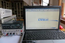
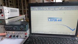
Output voltage is 3.6151 mVrms.
Referred to input (80dB gain) : 361.51nVrms (Agilent 34410A, 0-100kHz, gain 80dB, 50ohms in Input)
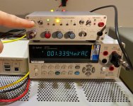
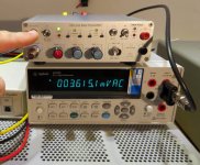
Look at the table (measurements.jpg) and other photos.
AndewT. Do the photos opened in full size? I see thumb only.
Last edited:
.....
Is that the 1.11 you are using?
I expected a correction of around 1.6
1.57 1-pole
1.11 2-pole butterworth
1.05 3-pole butterworth
1.00 Brick Wall
My is butterworth
Last edited:
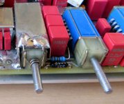
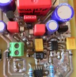
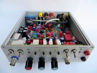
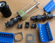
Inside
Attachments
-
 galette_shield.jpg322.8 KB · Views: 153
 -
 LTC1968.jpg245.5 KB · Views: 137
 -
 A-weight.jpg441.8 KB · Views: 125
 -
 inside_4.jpg267.3 KB · Views: 128
 -
 inside_3.jpg348.4 KB · Views: 166
 -
 inside_2.jpg259.1 KB · Views: 187
 -
 inside_1.jpg440 KB · Views: 152
 -
 component_top3.jpg354 KB · Views: 377
 -
 component_top2.jpg359.7 KB · Views: 413
 -
 component_top1.jpg401.6 KB · Views: 436
LNA noise measurement with Agilent 34410A:
Attachments
-
 noise-Input-0ohm-0Hz-100kHz-protected(499ohm serial thin film R)_gain80dB.jpg290.3 KB · Views: 84
 -
 noise-Input-50ohm-0Hz-100kHz-protected(499ohm serial thin film R)_gain80dB.jpg309.8 KB · Views: 75
 -
 noise-Input-0ohm-20Hz-20kHz_gain80dB.jpg395.2 KB · Views: 82
 -
 noise-Input-0ohm-1kHz-100kHz_gain80dB.jpg390.6 KB · Views: 87
 -
 noise-Input-0ohm-0Hz-100kHz-A-weight_gain80dB.jpg383 KB · Views: 86
 -
 noise-Input-0ohm-0Hz-100kHz_gain80dB.jpg387.9 KB · Views: 84
 -
 noise-Input-50ohm-20Hz-20kHz_gain80dB.jpg365.8 KB · Views: 79
 -
 noise-Input-50ohm-0Hz-100kHz-A-weight_gain80dB.jpg403.1 KB · Views: 125
 -
 noise-Input-50ohm-0Hz-100kHz_gain80dB.jpg338.5 KB · Views: 164
 -
 measurements.jpg178.1 KB · Views: 140
LNA noise measurement with Multi-Instruments
Attachments

STEP RESPONSE at: 10kHz, 100kHz, 500kHz, 1MHz
Attachments


- Status
- This old topic is closed. If you want to reopen this topic, contact a moderator using the "Report Post" button.
- Home
- Design & Build
- Equipment & Tools
- My implementation of Ultra Low Noise Preamplifier and RMS Meter