THANKS Salas!
If I were to AC couple when doing this, would I be reading the noise on the rails when measuring the difference between Vrail and Vgnd?
Thanks!
Surely. Demonstrably so.
Attachments
There is the modest CMRR two channel differential option too.
https://www.youtube.com/watch?v=VWodjUSkYVE
Nice tip
I see!
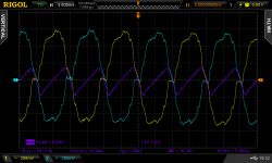
So the dark blue, CH1 + CH2 is the actual power supply ripple current.
Which means the yellow (CH1) and blue (CH2) channel traces are showing differential mode operation, including the noise, which is deviation from the perfect sine wave.
There does appear to be some common mode noise in the display, where the positive sides have a nipple on the top, while the negative sides have the same/similar rise in measured value.s
CH3 and CH4 could measure the output of a really good signal generator tuned to 100Hz. Then more math could remove the ripple from each polarity, showing the real noise on the rails.
Last edited:
I see!
So the dark blue, CH1 + CH2 is the actual power supply ripple current.
Which means the yellow (CH1) and blue (CH2) channel traces are showing differential mode operation, including the noise, which is deviation from the perfect sine wave.
There does appear to be some common mode noise in the display, where the positive sides have a nipple on the top, while the negative sides have the same/similar rise in measured value.s
CH3 and CH4 could measure the output of a really good signal generator tuned to 100Hz. Then more math could remove the ripple from each polarity, showing the real noise on the rails.
The DSO effectively escalates to three channels. Two physical and one virtual, the math purple one, which presents the addition of the two physical ones while one of those has invert selected in its main menu. On each physical channel we see the half bridge 50Hz waveforms. On the math channel we see their difference which is the 100Hz ripple voltage across the filter capacitor.
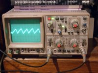
The CRO diminishes to one physical differential channel equivalent to the mentioned math channel in function. Inv and Add buttons are depressed if you watch the Hameg photo closely. Being analogue it can't keep showing everything because it does not store and compute. So just one trace, the differential result one, i.e. our main interest in this case.
Aha! invert channel two and add. Then only the differential noise remains.
Exactly.
")
*Not for too high frequencies or great SNR because two physical channels and probes plus a wide area can not compete to specialized active dif. probe, but useable and durable. 100-120Hz ripple isn't a challenge yet.
- Status
- This old topic is closed. If you want to reopen this topic, contact a moderator using the "Report Post" button.
- Home
- Design & Build
- Equipment & Tools
- Rigol DS1102E Oscilloscope