Hi All,
I'm trying to learn to how to read the schematic of a power supply in my DVD so that I can learn how to mod basic things such as replacing better capacitors, diode recifier bridge, and the x-rated capacitors around the transformer.
Can someone please take a look at the attached power supply schematic and help me identify the followings?
1) diode rectifier bridge. Are these this D11 - D14 in the schematic?
2) x-rated capactitors (not sure if i'm using the right words here, but it's basically what people normally replace with 2 Auricaps capacitors). Are these D102 and D107 in the diagram?
Thanks
Attachments
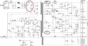
1. Yes D11-14 is the bridge diodes.You can use faster diodes.Make sure they are the same or better ( voltage rating).
2. D102/107 are schottky diodes.caps use the Cxx designation.
The X rated caps are already there in the form of a common mode filter.C1-2 which are normally of same value.Using Auricap is overkill in terms of price but you can check if they are polypropelene/MKP types instead of polyester/MKT.Note Auricaps are polyprops not polyester.Alternatively you can add another X rated MKP of different value say smaller one like 0.01-0.022uF to cover a wider range of noise shunting.Typically C1-2 are 0.1uF.BTW X1 or X2 are rated not to cause a fire so don't take chances.(add across the AC line input or somewhere appropriate,across AC live/ground).
You can add a small ceramic/multilayered ceramic 0.1uF to the various power supply decoupling caps to improve noise shunting.
Note--These maybe already on board in the form of small smt caps near the power supply pins of various ICs futher up the chain.
C105/106 =12V ( 0.01-022 /0.1uF,use a different value for each if applicable).
C unnamed /C109 =EVS5V
C110 = SW5V
C108/111 =SW3.3V
C112 = -28V
C301 =FLACA -- display panel
C303 = FLAB -- dispaly panel
Note -28V and display panel may be optional but getting rid of most noise helps.
Solder to the underneath of caps if no space available.
Let us know of the results. Regards.
SORRY! I made BIG MISTAKE. The X capacitor should be across AC LIVE and NEUTRAL, NOT ground.
Yes. agree with rfbrw that's it switch mode supply.Well it's up to newbie06,if it frightens you then don't do it.I have done a few switchers as long as you check that your connections are right and clean meaning no solder splashes or shorts it's worth a try unless you value the DVD very much.
Take care.I mean it.
Thanks for replying (and the warning) rfbrw and singa. I don't care if this DVD blows up so no worries.
Below is some more questions regarding your reply.
Please bear with me while I'm trying to learn this wonderful hobby.
#1 Understood
#2 What's Cxx designation and where I can find them?
Are you saying I can remove C112, C301 and C303? I don't really care about the display panel.
So where are the X-rated capacitors?
newbie06 said:I'm trying to learn to how to read the schematic of a power supply in my DVD so that I can learn how to mod basic things such as replacing better capacitors, diode recifier bridge, and the x-rated capacitors around the transformer.
Can someone please take a look at the attached power supply schematic and help me identify the followings?
1) diode rectifier bridge. Are these this D11 - D14 in the schematic?
2) x-rated capactitors (not sure if i'm using the right words here, but it's basically what people normally replace with 2 Auricaps capacitors). Are these D102 and D107 in the diagram?
This "modding" culture ranks right up (down?) there with "intelligent design" as one of the silliest and most wasteful expenditures of human energy ever devised.
Those parts were selected by a trained, experienced engineer who knew what he was doing. That poor guy gave up female companionship and all other remnants of a social life while he suffered through years of engineering school just so that he would be able to select parts for a circuit like that. What have you done that makes you better qualified to select those parts than he? Oh yeah, you read a post by some dope who didn't know anything on an on-line forum saying something about how x sounds better than y...
You will not get an education in forums like these. These forums are equivalent to masturbation. You expend a lot of energy and in the end, nothing is accomplished. Stop now, before you need glasses.
These forums are not for "newbies" or "noobs". As a noob, you do not have the knowledge required to recognize BS, hence you ask questions about identifying parts on a schematic because someone gave you the idea that by changing some of them you could magically improve the performance of the device. Go get a real education at a real school or at least in books written by people who know what they are talking about.
I_F
newbie06 said:Thanks for replying (and the warning) rfbrw and singa. I don't care if this DVD blows up so no worries.
You might if it takes you along for the ride. A switched-mode psu is not a safe place to learn the ropes.
I_Forgot,
There are many flaws in your reply, and I don't want to poin them out and let's just not go there.
If I get a few more replies like yours regarding this forum is not for newbies. I'll stop postings here. Until then, I'll just think that you're nothing but a bad tree in a jungle.
rfbrw, I understand. Thanks!
I think what I_Forgot did was to try to save your physical and mental health, though some of the words could have been choosen different. ")
Please don't mess around with a switch mode supply, you will never get good results. Every time you change components with "better ones", you change a lot of parameters that in the end will force you to also modify the filters, and at that time you will have as little hair as me
If you really want to "improve" the dvd, then maybe you should consider a conventional supply with BIG transformers, BIG capacitors and some good regulation.
A huge job yes, but with a lot better chance of success, and with lots less chance of ruining your health.
Best regards
Ebbe
Hi.
I agree.
Do not mess with a switch mode supply for any reason.
Even in the USA with 115vAC mains supply, the stored charge on the capacitors is lethal!
If you do want to start playing with your DVD, look at the audio output stages NOT the power supply. They are much simpler and non-lethal.
Andy
I agree.
Do not mess with a switch mode supply for any reason.
Even in the USA with 115vAC mains supply, the stored charge on the capacitors is lethal!
If you do want to start playing with your DVD, look at the audio output stages NOT the power supply. They are much simpler and non-lethal.
Andy
I say let evolution take its course! (Sorry, I'm in a vile mood today.  )
)
Those things you call "x-rated caps" have little to do with adult entertainment industry.
X and Y class capacitors are (usually metal film) capacitors specifically rated for duty across the line (X) and line to ground (Y) applications. This involves high voltage handling capability and flame retardance:
http://www.cde.com/catalogs/mexy.pdf
http://www.cde.com/catalogs/MPX.pdf
Do not replace them with arbitrary parts, especially since you have trouble finding them on schematics.
)Those things you call "x-rated caps" have little to do with adult entertainment industry.
X and Y class capacitors are (usually metal film) capacitors specifically rated for duty across the line (X) and line to ground (Y) applications. This involves high voltage handling capability and flame retardance:
http://www.cde.com/catalogs/mexy.pdf
http://www.cde.com/catalogs/MPX.pdf
Do not replace them with arbitrary parts, especially since you have trouble finding them on schematics.
newbie06 said:Hi All,
I'm trying to learn to how to read the schematic of a power supply in my DVD so that I can learn how to mod basic things such as replacing better capacitors, diode recifier bridge, and the x-rated capacitors around the transformer.
Can someone please take a look at the attached power supply schematic and help me identify the followings?
1) diode rectifier bridge. Are these this D11 - D14 in the schematic?
2) x-rated capactitors (not sure if i'm using the right words here, but it's basically what people normally replace with 2 Auricaps capacitors). Are these D102 and D107 in the diagram?
Thanks
Hi.
Since you ignore the warnings about not messing with switch mode supplies, let's get a bit more technical.
Obviously, you have seen in other threads, advice concerning replacing the diodes in a bridge for 'better' types etc.
99.9% of this advice is directed at conventional power supplies with transformer, bridge, capacitor, regulator etc. NOT switch-mode supplies.
Switch-mode supplies are a cheap alternative to a transformer supply. Inherantly, they are not hifi and as such there is little you can do to improve them. Certainly, changing the input bridge and X-caps would have almost no effect. Why? Switch-mode supplies do exactly what they say - switch the rectified mains supply on and off. So they produce vast amounts of HF garbage which it is almost impossible to get rid of.
The reason for changing the bridge rectifiers is to get rid of the minute amount of HF noise generated by the diodes - noise so tiny in a SMPS that it is swamped by the PSU noise itself.
A similar situation exists for changing the caps.
So, not only is it dangerous to play with SMPS, but it is also not worth the effort.
Build yourself a conventional, high-quality power supply, either to fit internally or in an external box. It is easier, better and safer!
Andy
singa said:
Hi singa,
yeah, let's just hope no balls will be lost on this trip
Thanks for the awesome link.
So can you confirm for me that the x-rated caps on my schematic is C9 and C10? I didn't quite understand what you said earlier.
newbie06 said:
So can you confirm for me that the x-rated caps on my schematic is C9 and C10? I didn't quite understand what you said earlier.
Hi newbie06,
I think you've misread my post the X caps are C1 and C2.Stradling the common mode choke/trans.If they are MKP then leave it alone.If not it also save cost by not replacing it.
C9 and C10 is part of the heart of the switchmode supply.Leave it alone
The article in the link should give you a clearer picture.Always check after soldering that you may inadvertantly leave solder splashes on the board.A magnifying glass is helpful.Good luck.
singa,
thanks for clarifying. Can you recommend any good book that would explain these things in details?
The schematic book I just brought from a local bookstore didn't help me locate these parts at all.
poynton,
If I get this working, I'll be more confident with other stuff. Thanks!
thanks for clarifying. Can you recommend any good book that would explain these things in details?
The schematic book I just brought from a local bookstore didn't help me locate these parts at all.
poynton,
If I get this working, I'll be more confident with other stuff. Thanks!
- Status
- This old topic is closed. If you want to reopen this topic, contact a moderator using the "Report Post" button.
- Home
- Source & Line
- Digital Source
- Identifying parts in this power supply