Is there any correlation between the longevity of CD lasers and the type of CD played?
Does the laser work harder to read a CD-RW compared to a factory pressed CD?
Or is it like shining a torch (with only one brightness setting) at something reflective which can then be seen by your eye compared to something less so, the result being "nothing to see here".
My understanding is as a laser unit gets older it provides less light and therefore the reflections are less so a tired laser will stop being able to read CD-RW first, then CD-R and eventually wont even read factory CDs.
I can also remember reading or hearing about some CD players having variable output lasers but that was not the norm. (sorry I can't remember from where).
The purpose of all this is that if it is kinder to a CD player to only play original pressings, I will refrain from playing any of my home burned compilations on my favourite player to make it last longer, but if it really makes no difference to the player itself and playing/or not playing CD-Rs and has no detrimental effect on the players longevity, then I will continue.
Many thanks in advance for any input.
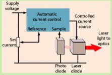
The laser runs at a constant optical power and that is monitored via a photo diode inbuilt and alongside the laser diode itself... they are fabricated onto the same die.
The type of CD has no effect on the laser operating conditions.
As the laser ages the optical power reduces and so to the energy received by the photo diode monitor which then compensates by increasing the laser current to maintain optical power output.
So you can keep playing whatever discs you like, the laser has no knowledge of what you are doing")
The type of CD has no effect on the laser operating conditions.
As the laser ages the optical power reduces and so to the energy received by the photo diode monitor which then compensates by increasing the laser current to maintain optical power output.
So you can keep playing whatever discs you like, the laser has no knowledge of what you are doing
Discs do have diffeent reflectivity though and as such, the Laser will compensate to a certain extent to maintain enough RF Level.
At least that's what I thought.
I was under the impression a Laser playing a marked or scratched Disc with poorer reflectivity had indeed to work 'harder'.
I could be wrong.
At least that's what I thought.
I was under the impression a Laser playing a marked or scratched Disc with poorer reflectivity had indeed to work 'harder'.
I could be wrong.
The different disc reflectivity shows up as a reduced RF level which goes a long way to indicating the laser output is constant and not adjusted to suit the disc.
Although having the laser power adjust to the disc seems a good idea it would be fraught with problems in practice over such things as response time and having to have max and min preset values. What would it do when trying to focus when no disc was present for example.
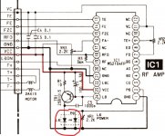
This shows a KSS240 which is typical of them all. The laser diode (LD) and photo diode (PD) are on the same die within the laser package. This photo diode has nothing to do with the multi photo diode array which is used to detect the reflected beam.
The laser current is set purely on the level of laser light hitting this PD detector. The circuit is designed to maintain a constant level of optical power such that the energy received by this diode is constant.
Although having the laser power adjust to the disc seems a good idea it would be fraught with problems in practice over such things as response time and having to have max and min preset values. What would it do when trying to focus when no disc was present for example.
This shows a KSS240 which is typical of them all. The laser diode (LD) and photo diode (PD) are on the same die within the laser package. This photo diode has nothing to do with the multi photo diode array which is used to detect the reflected beam.
The laser current is set purely on the level of laser light hitting this PD detector. The circuit is designed to maintain a constant level of optical power such that the energy received by this diode is constant.
Attachments
The IR light intensity emitted by the laser diode itself is fixed by the APC trimpot adjustment and does not change for different types of disc. The previous post in this thread explains it:
I think it is very easy to get confused about this.
In fact I'm writing this post to refresh my own memory about the differences between "Philips based" CD players with swing-arm transports (CDM-type) vs. Japanese CD players (with Sony, Hitachi, Sanyo, etc. laser pickups). I recently studied the service manuals & diyAudio posts for CD players with Philips "CDM" swing-arm pickups. I'm doing this because my newest project is the restoration of 4 Philips CD players.
There are 2 major design architectures. Each has a different procedure for adjusting IR laser light intensity:
Both varieties have an APC (automatic power control) circuit and a trimpot for adjusting emitted IR light intensity. What differs is the method for adjusting this trimpot.
Philips (CDM):
The Philips procedure for adjusting laser light intensity requires having a disc in the player in "play mode."
Then the trimpot gets adjusted to provide 50mV measured at test points on the main PC board. This voltage is directly proportional to the amount of light received by the ABCD optical receiver photodiodes inside the optical pickup. In other words this procedure measures the IR light intensity coming back into the optical pickup after being reflected from the disc. Therefore it will be slightly different for each disc.
Philips service manuals don't discuss the actual "emitted" IR light intensity (Measuring this requires a laser light meter such as the Leader LPM-8000). The Philips manuals also don't talk about the actual laser diode current (Iop).
Japanese (KSS-240AAA, HOP-M3, etc.):
Laser light output is measured with a "laser light meter" such as the Leader LPM-8000 and the APC trimpot is then adjusted to provide a specified light intensity measured in uW. Typical values are 100-500 uW. This measurement is performed by holding the detector probe of the light meter close to the lens of the laser pickup assembly.
No disc is needed.
Some Japanese service manuals state that "laser current (Iop) should be measured to make sure it is within spec." Generally the absolute maximum safe operating current for a laser diode is 70mA. Exceeding this will permanently destroy the laser diode. Typical operating currents after adjustment are from 40-50mA. Japanese optical pickups often have a label indicating the laser current (Iop, mA) measured during initial factory QC and sometimes also the emitted light intensity (uW). If later readjustment requires increasing the Iop by more than 5-10% to get the specified uW of light, then this indicates "end-of-life" for the optical pickup.
To summarize:
The Philips method for adjusting laser light intensity actually does measure the "reflected light" coming back from a disc. Therefore the choice of disc is important. Philips specifies one of their own special test discs, "test disc 5." Actually any factory pressed CD which is in good condition can be used. Some diyAudio members suggest taking an average among several discs. However, a CD-R or CD-RW should never be used for this procedure. They reflect less light than a factory disc.
The Japanese procedure requires a special tool (LPM-8000 or equivalent). No disc is needed.
For both varieties laser light intensity will remain constant after adjusting the APC trimpot. It will not vary for different discs.
-EB
This arrangement with a photodiode (PD) embedded inside the laser package is necessary because the amount of IR light emitted by a laser diode is very strongly affected by its temperature. Obtaining a constant amount of IR light requires an active feedback circuit to measure the IR light intensity and control the laser current accordingly. This active control circuit is known as the "APC" (automatic power control) circuit. There is almost always a trimpot for adjusting IR light intensity. It is often referred to as the "APC trimpot."This shows a KSS240 which is typical of them all. The laser diode (LD) and photo diode (PD) are on the same die within the laser package. This photo diode has nothing to do with the multi photo diode array which is used to detect the reflected beam. The laser current is set purely on the level of laser light hitting this PD detector. The circuit is designed to maintain a constant level of optical power such that the energy received by this diode is constant.
I think it is very easy to get confused about this.
In fact I'm writing this post to refresh my own memory about the differences between "Philips based" CD players with swing-arm transports (CDM-type) vs. Japanese CD players (with Sony, Hitachi, Sanyo, etc. laser pickups). I recently studied the service manuals & diyAudio posts for CD players with Philips "CDM" swing-arm pickups. I'm doing this because my newest project is the restoration of 4 Philips CD players.
There are 2 major design architectures. Each has a different procedure for adjusting IR laser light intensity:
1) Philips-based CD with "swing-arm" disc transport mechanisms (CDM1, CDM2, CDM4, etc.). The trimpot for adjusting laser light intensity is located on the main PC board.
2) Japanese laser pickups (Sony, Toshiba, Hitachi, Sanyo, etc.). The trimpot for adjusting laser light intensity is located on the optical pickup itself.
2) Japanese laser pickups (Sony, Toshiba, Hitachi, Sanyo, etc.). The trimpot for adjusting laser light intensity is located on the optical pickup itself.
Both varieties have an APC (automatic power control) circuit and a trimpot for adjusting emitted IR light intensity. What differs is the method for adjusting this trimpot.
Philips (CDM):
The Philips procedure for adjusting laser light intensity requires having a disc in the player in "play mode."
Then the trimpot gets adjusted to provide 50mV measured at test points on the main PC board. This voltage is directly proportional to the amount of light received by the ABCD optical receiver photodiodes inside the optical pickup. In other words this procedure measures the IR light intensity coming back into the optical pickup after being reflected from the disc. Therefore it will be slightly different for each disc.
Philips service manuals don't discuss the actual "emitted" IR light intensity (Measuring this requires a laser light meter such as the Leader LPM-8000). The Philips manuals also don't talk about the actual laser diode current (Iop).
Japanese (KSS-240AAA, HOP-M3, etc.):
Laser light output is measured with a "laser light meter" such as the Leader LPM-8000 and the APC trimpot is then adjusted to provide a specified light intensity measured in uW. Typical values are 100-500 uW. This measurement is performed by holding the detector probe of the light meter close to the lens of the laser pickup assembly.
No disc is needed.
Some Japanese service manuals state that "laser current (Iop) should be measured to make sure it is within spec." Generally the absolute maximum safe operating current for a laser diode is 70mA. Exceeding this will permanently destroy the laser diode. Typical operating currents after adjustment are from 40-50mA. Japanese optical pickups often have a label indicating the laser current (Iop, mA) measured during initial factory QC and sometimes also the emitted light intensity (uW). If later readjustment requires increasing the Iop by more than 5-10% to get the specified uW of light, then this indicates "end-of-life" for the optical pickup.
To summarize:
The Philips method for adjusting laser light intensity actually does measure the "reflected light" coming back from a disc. Therefore the choice of disc is important. Philips specifies one of their own special test discs, "test disc 5." Actually any factory pressed CD which is in good condition can be used. Some diyAudio members suggest taking an average among several discs. However, a CD-R or CD-RW should never be used for this procedure. They reflect less light than a factory disc.
The Japanese procedure requires a special tool (LPM-8000 or equivalent). No disc is needed.
For both varieties laser light intensity will remain constant after adjusting the APC trimpot. It will not vary for different discs.
-EB
As a Sony approved service centre we had to have all the stuff like laser power meters and so on... what a waste of money, I don't think we ever used them that I can recall. They were finnicky and even slight movement of the detector changed the reading enormously.
The Philips method was always interesting because what they are saying in effect is that you turn the power up as much as is needed to get the required level of RF when using a disc of known reflectivity.
I always used a known good disc (actually some Philips test CD's) and set/checked that the RF met the 1.2 to 1.5v peak to peak standard. Same for any players using KSS pickups if it was felt needed to confirm all was well.
I seem to remember the Philips swing arm mechs used the Sharp LT022MC (was it???) laser diode and the specs on those had a maximum current/optical output quite a bit higher than the pickups of the day called for. In other words they were under run well below max ratings.
I have a Leader LPM-8000 laser power meter. I purchased it way back in the late 1980’s when I operated the repair department of a local Audio/Video retail store. I still use it now to confirm IR light intensity for optical pickups. I find that it is easy to use when the CD player can be put into a “service mode” where the laser stays on continuously. I haven’t observed any issues with errors caused by probe position. The probe on my IR light meter is flat and the sensor is about 10mm diameter. I position the probe directly over the laser pickup lens to take measurements. I’m finding that optical pickups which are in good condition typically have IR light intensity close to the manufacturer’s spec.As a Sony approved service centre we had to have all the stuff like laser power meters and so on... what a waste of money, I don't think we ever used them that I can recall. They were finnicky and even slight movement of the detector changed the reading enormously.
Curiously, Philips doesn’t appear to publish specs for IR light intensity or actual laser current (Iop) for their CDM optical pickups. I’m compiling a chart for this as I work on a stack of Philips CD players with CDM2 and CDM4 pickups. The chart will show the measured IR intensity (uW) and laser current (Iop) for normal operation after having adjusted the trimpot on the PC board to get the Philips-specified 50mV across the 4K7 monitoring resistor. I’m adjusting the trimpot to get an average of 50mV measured among several discs.
Right now I have a Magnavox CDB480 on the bench where the data is 100uW emitted IR intensity and 70mA Iop. Note: I’m measuring Iop by the voltage drop across the 16 ohm resistor in series with the laser drive transistor. This player is working well. To me Iop=70mA seems high, but since this is the first CDM pickup I’ve measured I don’t yet have enough data to make conclusions.
-EB
Good to hear you find your LPM useful. I do remember we did not get on with ours, it just never got used.
70ma does sound high compared to the values seen on Sony type pickups which I recall were around the 45 to 55ma region. Measuring across the resistor is the correct way, just remember that if the resistor is in the emitter then the base current is added in to that result as well... only going to be a couple of milliamps at a guess though.
Philips were always weird in their test and alignment procedures. TV's and VCR's were just the same. I always rated the service manuals though as being very clear. I was in a minority there.
I've always wondered how cloudy optics affect the recovered RF level and whether any effects or reduction there also shows when looking at the overall intensity, for example with a LPM.
I did my math wrong. The resistor is 18 ohms, but (somehow) I used 16 ohms for my first set of calculations.70ma does sound high compared to the values seen on Sony type pickups which I recall were around the 45 to 55ma region.
The actual laser current (Iop) for the CDM4 in my Magnavox CD player is 60mA.
Not 70mA.
I measured again after adjusting the trimpots according to service manual:
50mV across 4K7 resistor.
400mV at focus servo test point.
400mV at focus servo test point.
The result: Iop=60mA
Because the light beam must pass through the lens in both directions I would expect a dirty/cloudy lens to reduce RF signal amplitude considerably.I've always wondered how cloudy optics affect the recovered RF level and whether any effects or reduction there also shows when looking at the overall intensity, for example with a LPM.
I cleaned the external surface of the lens.
I haven't tried removing the focus actuator assembly to clean underneath.
-EB
Because the light beam must pass through the lens in both directions I would expect a dirty/cloudy lens to reduce RF signal amplitude considerably.
I cleaned the external surface of the lens.
I haven't tried removing the focus actuator assembly to clean underneath.
-EB
And this is where the differences in measurement techniques will show. The Sony method of having a known Iop (set at manufacture) printed on the pickup does not account for anything that reduces the emitted IR from the objective lens in years to come. The level was set correctly when new and provided the laser diode remains good then the Iop is unchanging. Even if you cover the LD up the power setting still remains correct.
The Philips method of 50mv across a resistor does account for losses in the transmission path and so the current is set to whatever value is needed to reach the 50mv level. If the optics are cloudy then the current may be quite high but as far as the specification goes, the pickup still meets its spec.
Interesting
Most optical pickups of Japanese origin have a printed label stating the original factory Iop (mA).The Sony method of having a known Iop (set at manufacture) printed on the pickup does not account for anything that reduces the emitted IR from the objective lens in years to come. The level was set correctly when new and provided the laser diode remains good then the Iop is unchanging.
If the trimpot hasn’t been disturbed then Iop measurement provides a useful “health check” for the laser diode. If Iop is still within 5-10% of the original factory value then the laser diode is in excellent condition. Disclaimer: There may be faults in other sections of the optical pickup assembly which prevent it from functioning even though the laser diode itself is still good. Examples: Faulty light sensor diodes (ABCD & EF), dirty/fogged/misaligned optics, damaged focus/tracking actuator assembly...
In contrast a faulty laser diode will have a very high Iop (it may exceed 100mA). At the same time the emitted IR intensity will be very low or none at all. In this case the optical pickup is unusable except for those brave souls who have succeeded at replacing the laser diode without destroying the rest of the optical pickup.
I’m making a habit of measuring Iop (mA) and emitted IR light intensity (uW) prior to making any adjustment of the trimpot.
And as I work through my collection (hoard?) of vintage CD players I’m collecting data for Iop (mA), IR light intensity (uW), and RF signal eye pattern amplitude (volts P-P) for every machine. These 3 parameters should be closely related to each other. Unfortunately not every service manual provides specs for all three items.
-EB
- Home
- Source & Line
- Digital Source
- CD-Rs and Laser Life?