Hello. I've changed successfully some laser diodes in KSS-272A, KSS-271A, old OPH32 or similars, VWY061 Pioneer and etc...
I wanted to do the same with some KSS-151A, but all I have are working correctly, and is a nonsense to do experiments in good working laser devices. In the last month I bought a faulty Sony CDP-337ESD complete, faulty but in good condition. The laser was exausted, 0.5V RF signal and 116mA, the power out is noted in my notes, I don't remember. This is was the perfect candidate.
The KSS-190A and the KSS-151A are electrically equals. The extension cable I build is useful for both.
For to replace and adjust the KSS-190A I used the Denon DCD1500II, which uses the KSS-190A. Is a broken cd that works, and is useful for to experiment.
First, I build the cable extensor. But there was a problem, the amplifier I built for the KSS-272a and other lasers pickup was not very apropiate. I saw that the perfect amplifier was a I-V amplifer. Well, I constructed it with tiny modifications, and it worked.
Then, dismantle the KSS-190A, I replaced the laser diode and assembled another time.
Well, like other times with this things, the first time was with bad signal, and is normal, the device was totally dismantled and now must be adjusted.
Now is working with 1.2V and very clean signal, but must be realigned, the adjuste performed is the most principal.
This procedure is applicable for the KSS-151A. The perform of changing the laser diode should be more easy in the KSS-151A.
If you see the two black filter capacitors, this cd looks like it were used a lot.
There is another curious thing. This cd uses the infamius Elna Duorex II capacitors, however in this cd all are in good state, in spite this cd is older than in the models that these Duorex produces problems, like in the CDP-X33ES.
I've seen that the 7805 regulator have been changed, by a Texas Instruments 7805, and the relays too.
Some pics, some videos, etc...
Sony KSS 190A with new laser diode with adjusting waves - YouTube
Sony CDP 337esd KSS 190A with new laser diode - YouTube
KSS-190A replace diode and KSS-151A measurements - Google Photos
Hi ManoloMos,
It's great news that you've succeeded in performing a laser diode swap on the KSS-190a, there were some great machines built with this pick-up that need to be saved from the scrap heap!
I have already managed to do a diode replacement on a BU-1C following your instructions and I'd like to have a try with a KSS-190a when a suitable faulty player shows up. Please can you tell me more about the amplifier circuit that you built?
I'd be interested to know if you've looked at the KSS-150a or KSS-210a head too. It looks to me that a diode swap might be relatively easy on the KSS-210a.
Hello. I'll do some notes and draws next thursday.
By the moment, you'll need
-. Flex cable extensor, 16 pin for KSS-151, KSS-190A, etc... and if you want, 20 pin for KSS-272A, KSS-271A, etc...
10 Uds., 200mm, 20 pines, 20p, 1,25mm, cable plano Flexible FFC, cinta de alambre, avance directo tipo A|Kits de domotica| - AliExpress
-. Flex connector female, 16 and 20 pin 1.25mm pitch.
Molex FFC/FPC Agujero Pasante 5597 serie 1.25 mm pitch 20 Vias Recto Hembra FPC C | eBay
-. Things for to do the grasp for the laser unit.
-. Mirror.
-. +15V -15V Power supply
-. Oscilloscopes, four channels minimun, six is better.
Flex cable extender is 1.25mm pitch.
The Op amp I used is AD826, a double operational. It doesn't have to be it, it can be another, for example LF353, etc...
I have to do a better DC+Sinus signal for the Focul Coil circuit. With a power supply and a signal generator is OK, but it is not he best option. I'll copy and try with some coil circuit with transistors of some old CD
The grasp of the pickup for the KSS-272A is useful for the KSS-271A and the KSS-190A, but not for the KSS-151A.
This method should be good for the BU-1 units but, if the method of changing the diode and adjusting the diode angle with the screws works, I'd still use this method. Is relatively easy, it works...
In my KSS-190A, the new diode is the RLD-78MYA, it gives 192uW at lens, and consumes 44.5mA.s
Some pics.
KSS-190A KSS-151A interface - Google Photos
The KSS-190A has a good virtue, and is that avoid the dust, is relatively closed and this is good.
I have KSS-151A, from the Denon DCD-1500II, it gives 150uW and consumes 69mA. 1.2V RF signal. The RF is clean but has an extrange distortion in the bottom zone, but it works. This gives us a idea of the variety of currents, power and other parameters, that are not exactly the same from a laser pickup to another.
Thanks for the details. Unfortunately it sounds like the procedure is too complex for me as I only have a single dual trace 'scope.
I'd like to attempt a diode replacement in a KSS-210 or KSS-150 sometime as the current production replacements are poor quality compared to the originals.
I have worked on a lot of Sony ES players, most of them stuffed full of Elna Duorex capacitors and I have yet to see a bad one. I think the problem ones must be limited to certain production runs.
Last edited:
The KSS-150A original, not the clones, is ideal to get practice, and if you repair it, I think it worth. Original KSS-150A are not cheap. Maybe the only problem is the cable, there are two cables with two Molex connectors. But this is a minor problem.
If you see, in the KSS-150, 151, 152, 190, is very ingenious the way of to transport the tiny signal from the photodiodes to the IC CXA1081. It is due because it uses an I-V amplifier at the CXA1081. You put the oscilloscope at the photodiode signals in the CXA1081 and you can't see anything, however it works.
For this, I had to do another I-V amplifier for this laser pickup. I think this amplifier is good too for other pickups. The first amplifier I did for the KSS-274a now looks very complex and not practical.
Now I want to do a circuit for to drive the Focus Coil with improved precision. The way I do with a power supply and a signal generator works, but it is not the ideal.
Thanks for the details. Unfortunately it sounds like the procedure is too complex for me as I only have a single dual trace 'scope.
I'd like to attempt a diode replacement in a KSS-210 or KSS-150 sometime as the current production replacements are poor quality compared to the originals.
I have worked on a lot of Sony ES players, most of them stuffed full of Elna Duorex capacitors and I have yet to see a bad one. I think the problem ones must be limited to certain production runs.
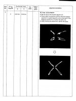
A way to see all signals in one oscilloscope is to transform the four signals in this Lissajous wave. For me is more easy to do that in three oscilloscopes that to design and do a circuit for to do this. This picture is taken from the Pioneer P-D70 Service Manual.
Attachments
Hi. I've done a circuit for to drive the focus coils. It is powered by the +-15V, and the AC signal from a waveform generator. The circuits is a adder of these signals, and a low impedance buffer for to atack the coils. The DC voltage is varied by a multiturn potentiometer. And the most important, it works. In the video you can see the signals from the A B C D photodiodes of a KSS-151A unit, with original laser diode, it haven't been replaced because the unit is good.
If I have time I'll draw the circuits. Some years ago I used to draw circuits in OrCad, but now the circuits it is drawn by pen. Nothing is perfect.
KSS 151A with original Laser Diode, A B C and D photodiodes testing signals - YouTube
If I have time I'll draw the circuits. Some years ago I used to draw circuits in OrCad, but now the circuits it is drawn by pen. Nothing is perfect.
KSS 151A with original Laser Diode, A B C and D photodiodes testing signals - YouTube
Very interesting Work.
check out also this threads:
Laser Diode Successor of SLD-104U for SONY ESPRIT KSS Series
KSS-272A Substitution of laser diode
check out also this threads:
Laser Diode Successor of SLD-104U for SONY ESPRIT KSS Series
KSS-272A Substitution of laser diode
I've realised that the procedure in the service manual for to adjust, is good for normal or good discs, while if you want to adjust for problematic discs like CDR or scratched discs, service manual is not good. How do we adjust it?
Focus Bias and E-F balance, the best RF signal with a good disc and a track in the midle.
RF-PLL like manual says.
The rest... Focus Gain and Tracking Gain, is a mistery for me, so, essay-error with bad discs until getting the best perform.
Focus Bias and E-F balance, the best RF signal with a good disc and a track in the midle.
RF-PLL like manual says.
The rest... Focus Gain and Tracking Gain, is a mistery for me, so, essay-error with bad discs until getting the best perform.
Yes, I'd say that method is correct. I've realized of this too, but to get "the point" of the sound is not easy.
Here some pics of another KSS-190a and other horrible video, sorry...
KSS-190A #2 - Google Photos
KSS 190a #2 - YouTube
Here some pics of another KSS-190a and other horrible video, sorry...
KSS-190A #2 - Google Photos
KSS 190a #2 - YouTube
Ebay, Aliexpress and other online shops are floods of new KSS-151a, but if you prest attention carefully, they have some differences to original KSS-151A. If you see some ads, alls put in current data 658, that means 65.8ma. I'm not very strict if it is fake or original, for me the most important is its functionality. I'm temted to buy some of them for to see its performance.
Modulo de cabeza de canal unico tipo Puerto OC KSS 151A excitacion electrica de baja velocidad|Medidores de energia| - AliExpress
Modulo de cabeza de canal unico tipo Puerto OC KSS 151A excitacion electrica de baja velocidad|Medidores de energia| - AliExpress
Hello,
I bought one of these chinese KSS 151 a few months ago.
I put it in a CDP 228ESD and it works perfectly. After the replacement, no adjustment was necessary. The photos that can be seen everywhere are almost all the same.
What I understood is that these are reused old blocks but whose optical path has been cleaned and whose diode has been replaced.
In fact it is exactly what we try to do here") ...
...
I bought one of these chinese KSS 151 a few months ago.
I put it in a CDP 228ESD and it works perfectly. After the replacement, no adjustment was necessary. The photos that can be seen everywhere are almost all the same.
What I understood is that these are reused old blocks but whose optical path has been cleaned and whose diode has been replaced.
In fact it is exactly what we try to do here
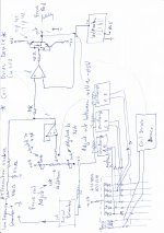
...This is the schemy of the focus coil exciter I made.
As you can see, is adder of DC and AC, DC comes from a voltage divider, and the AC from an external low frequency generator. Then is buffered and goes to the coil. You can add a chinese voltimeter for to see the out dc voltage. I adjusted to +1V and -0.5V.
As you can see, is adder of DC and AC, DC comes from a voltage divider, and the AC from an external low frequency generator. Then is buffered and goes to the coil. You can add a chinese voltimeter for to see the out dc voltage. I adjusted to +1V and -0.5V.
Attachments
Yes, the KSS-190A, 151A, BU-1 and a lot more pickups are similar, formed by a Photodiode array, diode laser, and coils.
KSS-151A and KSS-190A flex cable are equals, but BU-1 and similars not.
Here a table with some KSS Flex Cable pins data:
Dropbox - KSS pineado.odt
KSS-151A and KSS-190A flex cable are equals, but BU-1 and similars not.
Here a table with some KSS Flex Cable pins data:
Dropbox - KSS pineado.odt
- Home
- Source & Line
- Digital Source
- KSS-190A with new laser diode. Applicable for the KSS-151A too.