Hello to all this is my first post on this forum. I own a MARANTZ CD5005 and I have done following upgrade:
I have also used bitumen pads where I could , changed analog power supply cable with a shielded one and used some ferrite rings.
I would like to improve the clock. I have also measured with the oscilloscope the clock and it does not seem very stable you can see in the video as soon as I am being able to attached it.
I have written to Tent labs and Guido told me that its clock is not compatible with 1.8V power supply of the IC27 CDCE913PWR.
On the other side Fidelity audio suggested me to buy their C3 PRO Low Jitter Clock...
I have measured a Clock signal at pin 11 of IC27 and it has a Vpp of about 3.2V... IC27 power internal power supply is 1.8V , but the chip uses for teh outputs 3.3 V power supply, so I imagine that the output clock of Vpp 3.2 V is been supllied from 3.3V
What I can do to improve the clock..
Can anyone help me?
Thanks to all.
CD5005 tweakings fotos:


Video Clock Signal
https://mega.nz/file/2kp3wYrZ#1Xr1gYQw5BFdsH7usXMYZ9Eg_KbGV-IZd_4qMTrBT4s
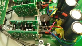
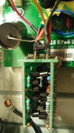
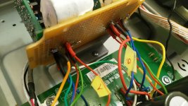
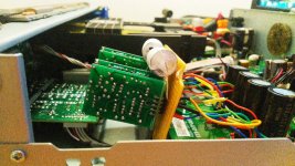
Image of clock wiring


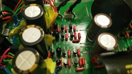
- Changed all electrolytic capacitors of the analog and digital PSU. I added also some bypass (Audyn QS6 0.47 uF and Chinese MKP 400 V 1.5 uF). I have substituted N4003 Diodes with UF4007 (I had already) and for the output stage I have used Schottky diodes. Moreover I have bought from aliexpress some discrete voltage regulator and they works great.
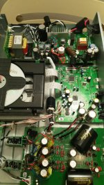
LINK: Hi end Class DC to DC Transistor Discrete Linear High Speed Regulator Module Voltage Regulator Replace LM78XX Upgrade LT317|Battery Accessories| - AliExpress - Changed all the electrolytic capacitors of the digital board inclusive the ones the DAC (Elna Silmic II oversized). This was the first big tremendous step in having a wide stage and monster bass...my neighbor have noted...🙂
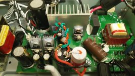
- Changed all the Mylar capacitor of the output stage with Amtrans AMCH, changed all resistors with PRP PR9372 Series Metal film, changed all electrolytic with Nichicon KZ and SIMIC II, de soldered the SMD opamp NJM2068 and installed discrete Op amp bought in aliexpress. (1pcs HIFI OP03 Full Discrete Component Field Effect Input Dual Op Amp Module Model Parts|Parts & Accessories| - AliExpress Used 10uF Audyn cap QS6 decoupling capacitor instead of the 100uf electrolytic.
I have also used bitumen pads where I could , changed analog power supply cable with a shielded one and used some ferrite rings.
I would like to improve the clock. I have also measured with the oscilloscope the clock and it does not seem very stable you can see in the video as soon as I am being able to attached it.
I have written to Tent labs and Guido told me that its clock is not compatible with 1.8V power supply of the IC27 CDCE913PWR.
On the other side Fidelity audio suggested me to buy their C3 PRO Low Jitter Clock...
I have measured a Clock signal at pin 11 of IC27 and it has a Vpp of about 3.2V... IC27 power internal power supply is 1.8V , but the chip uses for teh outputs 3.3 V power supply, so I imagine that the output clock of Vpp 3.2 V is been supllied from 3.3V
What I can do to improve the clock..
Can anyone help me?
Thanks to all.
CD5005 tweakings fotos:
Video Clock Signal
https://mega.nz/file/2kp3wYrZ#1Xr1gYQw5BFdsH7usXMYZ9Eg_KbGV-IZd_4qMTrBT4s
Image of clock wiring
Last edited:
I try to upload the images, video and manual, because I see it does not work correctly.
Attachments
-
Digital board_.pdf878.9 KB · Views: 237
-
 WhatsApp Image 2020-10-17 at 23.41.48.jpeg192.1 KB · Views: 463
 -
 WhatsApp Image 2020-10-17 at 23.41.47.jpeg167 KB · Views: 355
 -
 WhatsApp Image 2020-10-17 at 23.41.47(5).jpeg202.8 KB · Views: 312
 -
 WhatsApp Image 2020-10-17 at 23.41.47(4).jpeg173.2 KB · Views: 253
 -
 WhatsApp Image 2020-10-17 at 23.41.47(3).jpeg172.7 KB · Views: 265
 -
 WhatsApp Image 2020-10-17 at 23.41.47(2).jpeg145.1 KB · Views: 285
 -
 WhatsApp Image 2020-10-17 at 23.41.47(1).jpeg138.3 KB · Views: 250
First reply, though it is not helpful anyway. =) I got impressed with your upgrade. I also have this one and hope your upgrade keeps going.
Hello to all. I made another upgrade. If the previous ones broght the CD player to details , more bass and frequencies extension, 3D stage...
This one broght power in all frequencies. Volume seems to be higher to.
This is a MUST!!😱😱😱😱😱😱 You will be schocked. Of course you have to make also teh previous modifications.
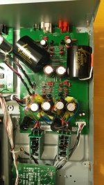
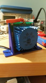
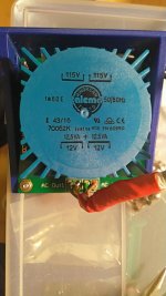
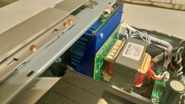
I added a TALEMA 25VA extra transformer for the only analogic output stage. I had already so many uF in all the capacitors which eventially could not be feeded from the original weak transformer.
Now digital and analogic power signal are completely separated.
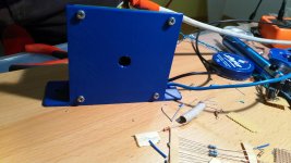
I bought the PCB for TALEMA Transformer fromm Aliexpress. Then I draw in CAD a 3D Model for the transformer support and let it in 3D printed.
There is only one space where it can be fitted and it is between the original transformer and the frontal panel. iT is a question of 1 mm maybe.
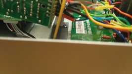
I cut the supply cable after the relay and joined with A mammuth connector to the two transformer.
I have measured the phase of the cable so that everything will be like before.
New transformer has been connected to the PCB using the old conncetor. Cable is 0.5 mm2 shielded.
Moreover I made also with a 3D PRinter a little support for teh discrete operational amplifier. Now they are really tought fixed on the chassis.
This one broght power in all frequencies. Volume seems to be higher to.
This is a MUST!!😱😱😱😱😱😱 You will be schocked. Of course you have to make also teh previous modifications.
I added a TALEMA 25VA extra transformer for the only analogic output stage. I had already so many uF in all the capacitors which eventially could not be feeded from the original weak transformer.
Now digital and analogic power signal are completely separated.
I bought the PCB for TALEMA Transformer fromm Aliexpress. Then I draw in CAD a 3D Model for the transformer support and let it in 3D printed.
There is only one space where it can be fitted and it is between the original transformer and the frontal panel. iT is a question of 1 mm maybe.
I cut the supply cable after the relay and joined with A mammuth connector to the two transformer.
I have measured the phase of the cable so that everything will be like before.
New transformer has been connected to the PCB using the old conncetor. Cable is 0.5 mm2 shielded.
Moreover I made also with a 3D PRinter a little support for teh discrete operational amplifier. Now they are really tought fixed on the chassis.
Attachments
-
 01 Supporto non montato.jpg850.5 KB · Views: 167
 -
 02 Supporto non montato.jpg440.4 KB · Views: 152
 -
 03 Supporto non montato.jpg461.6 KB · Views: 139
 -
 05 Supporto montato.jpg989.9 KB · Views: 198
 -
 06 Supporto operazionali.jpg870 KB · Views: 161
 -
 07 Supporto operazionali.jpg954.8 KB · Views: 149
 -
 08 Supporto operazionali.jpg168.2 KB · Views: 173