Hello. I've tried to know how to change the laser diodes in the CDs laser pickup and today finally I've changed a diode in a KSS-272A successfully.
As in other thread about the KSS-190A I said, I tried to change the diode laser and to adjust it, but it don't work. It works in KSS-121A and BU-1C, but no in KSS-272A.
For to adjust the KSS-272A, and others I suppose, you have to adjust the position of the Photodiode array IC. This is main trick.
This is the process.
1) Remove the diode, remove all the glue, clean it, blow with air under pressure.
2) Then place the new diode, type M (both diodes with common cathode), I put a Rohm RLD-78MA. Put glue, I used glue of two components. Wait until the glue is dry.
3) I change all potentiometers. Original are right, but are very hard for to manipulate. All are 2k2.
4) In the photodiode array Ic, remove the glue
5) Place the laser pickup in the mirror, with the 2mm pcb with a hole for the light to the laser.
As I said in the other thread, you force the laser ouput, extend the laser cable and cut the focus conection. In focus conection you conect a power supply(no more than 1 volt) and a low frequency generator.
6) Conect the A-B-C-D-E-F to a signal amplificator, six amplifiers in fact, and conect it to the oscilloscopes.
7) Place a piece of plastic in the fotodiode array with soft glue. It is used for to grab the fotodiode array with care.
8) Conect all, power up the CD, and find the signal. The first signal in appearing are the E-F signals. They are very usefully for to find the signal. In my case the power supply is 700mvdc and the signal generator between 21 or 23hz and between -4dbm or 0dbm.
9) Then you try to find the point like in the pictures appears, where A and C and B and D must be in phase, but 180º disphased between AB and CD. You must build a device like mine with a screew for to lock wheh yo have the right signal.
10) The signal is right and the screw lock the photodiode array for it can't be moved. Now you put glue where you retired the original factory blue. Wait until the glue is dry.
11) Now, without the screw lock the photodiode, you must confirm the signal is right.
12) Install the laser pickup and and ajust power laser and focus. And yes, it's difficult, for this in the point 3 I changed the potentiometers.
The laser power at the output for 1,5Vpp are 204uW.
There's only one problem, in my case the focus potentiometer is all at the left, the signal is clean but I think it could be more clean. I think it's due the RLD-78MA diode is different than the original, and the tolerance is at the limit.
I hope do the experiment again with other diodes that I've purchase and are on way. I want to do the experiment with a KSS-151A too.
I don't have any KSS-190A, but the process must be equal like KSS-151A.
Some pictures. I know, I'm not a great photographer, and the workshop is mess but, what workshop isn't?
KSS-272A June 2020 - Google Photos
Regards
Hello. This is the second KSS-272A with new laser diode, changed successfully.
The RF output was a bit weak, and few years ago I had to adjust of position of the piece which contains the coils and the movil lens. I don't know why happened this kind of disajustment.
Well, like the other laser pickup, I removed the laser and clean the zone. I checked the laser and... ohh surprise! The output laser was right, 6-7mw.
Anyway I changed the laser diode of a Rohm RLD78-MYA. The former laser pickup was a Rohm RLD78-MA. I placed the diode, glue, and to wait.
Then, I placed the piece which contains the lens and coils in right form, because years ago I moved it like I said.
Then, I removed the photoarray glue, unstick the photodiode array and clean the zone, then air with pressure.
Then adjust, like always, a-b-c-d-e-f diode signals at the oscilloscope. This time the adjust point was more difficult, or it seemed to me. The DC focus offset was 400mv, the other pickup 700mv. Is this difference due to use different diodes? I don't know.
Then, when I got the right signal, lock with a screw, glue, and to waiting to dry.
One day afterward, today, I placed the diode. I had to adjust another time the place of the piece which contains the lens and the coils.
Focus Offset was not critical, but Tracking Offset or Tracking Balance potentiometer was crucial.
Laser power at the lens is 150uW and 1.6V RF output with a good cd.
The process is very summarized, but it get a lot of time and work. It is not easy, at least for me.
Some pics and some videos. Regards.
KSS-272A nº2 Junio 2020 - Google Photos
YouTube
YouTube
Last edited:
The eyepattern looks extremely well! Congratulations. You are the first one on diyaudio
-besides some guy who claimed to do this but never did show how- who proved that a diode swap can be done!
CD will now live forever!
-besides some guy who claimed to do this but never did show how- who proved that a diode swap can be done!
CD will now live forever!
Thank you. All this was possible thanks to the cd manual of the Pioneer P-D70 and a tutorial of Pioneer about this CD. In this manual appears how the cd laser are adjusted in factory, is not clear but was the clue.
As I said, in some pickups, like KSS-121A, BU-1, the laser can be replaced and adjusted moving slighly the diode.
In the KSS-272A and similar, it is not possible with this method.
I hope in the few weeks do it again with a KSS-271A , that is very similar to the KSS-272A, with different diodes.
I've bought the FFC/FPC cable of twenty contacts and 1.25mm separation for to try with the KSS-151A.
I hope it works, because it will mean that it will work with the KSS-190A, that is very rare. KSS-151A and KSS-190A are electrically and optically similar.
If you see, all this lasers are basically the same with the same optic block: KSS151A, KSS152A, KSS190A, KSS270A, KSS271A, KSS272A, KSS273A, KSS274A, KSS280A and KSS281A.
If you know how to do with one, you must know how to do with all.
I'd like to design a very precise power supply from -1V to +1V with the possibility of to add the low frequency signal for to excite the focus coils, the point where you find the right focus is very exact, as you see in the video with the oscilloscopes.
One last thing. The first KSS-272A has a little more of noise than the second, however, the first is able to read a CD-writed cd with a lot of scratches, the second reads this cd, but with difficult. Curious.
Regards
This is very interesting as a very good book
about maintaining Compact Disk Players was written by Ken Klements,
a Pioneer and Sony technician. Nevertheless alignment was not covered much.
about maintaining Compact Disk Players was written by Ken Klements,
a Pioneer and Sony technician. Nevertheless alignment was not covered much.
.....I removed the laser and clean the zone. I checked the laser and... ohh surprise! The output laser was right, 6-7mw.
It would have been interesting if you had reassembled the Laser Block at this point, I suspect it may have worked.
In my experience repairing CD Players, very few emitting Diodes have failed, it is usually the Receiving Diode array or more likely dust where it's ''not usually'' accessible.
You have proved that it is accessible and a good clean 'probably' cured your problem.
I slute your perseverence !!
This is very interesting as a very good book
about maintaining Compact Disk Players was written by Ken Klements,
a Pioneer and Sony technician. Nevertheless alignment was not covered much.
Ken was (I don't know if he's still alive) a lovely fellow.
I attended many Training courses at Pioneer UK with Ken leading proceedings.
I would like a copy of his book but they have become very expensive and rare !!
ManoloMos,
Thank you for sharing your excellent work. I own a CDP with KSS-151A pick-up and are looking forward to your experiment again on changing the laser diode.
Thank you for sharing your excellent work. I own a CDP with KSS-151A pick-up and are looking forward to your experiment again on changing the laser diode.
Tried to contact Ken Klements for my laser diode swap project.
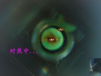
There are some photos floating arond by laser repairers
What struck me was the fact that one can see the beam spots
superimposed over the photodiode-array spots.
Maybe this effect can be used for aligning?
See photos below:
There are some photos floating arond by laser repairers
What struck me was the fact that one can see the beam spots
superimposed over the photodiode-array spots.
Maybe this effect can be used for aligning?
See photos below:
Attachments

Last edited:
ManoloMos,
Thank you for sharing your excellent work. I own a CDP with KSS-151A pick-up and are looking forward to your experiment again on changing the laser diode.
Hello. I've bought some ffc/fpc 20 pin 1,25 pitch cables and connectors for the KSS-151A, I'll try to change the diode laser in an KSS-151A and I'll tell in this forum.
For the KSS-151A we have to do a little circuit, to polarizase each a-b-c-d-e-f diode separately. I have to do this circuit because in almost all CD's player with KSS-151A or KSS-190A, the A C and B D diodes are joined, we need to see these diodes serparately.
Tried to contact Ken Klements for my laser diode swap project.
There are some photos floating arond by laser repairers
What struck me was the fact that one can see the beam spots
superimposed over the photodiode-array spots.
Maybe this effect can be used for aligning?
See photos below:
Hello. No, in fact, I doubt that in reality, the laser impact in the photodiode array be like in this picture.
If you see, almost all laser pickups has a part when you can see the A-B-C-D-E-F diodes. This makes me think that the method used in factory for to adjst the laser diodes is with a machine reading the A...F diodes. To adjust it, you have to put a mirror front the pickup, and to excite the focus coil with low frequency signal and a bit of dc voltage.
When you are triying to adjust the laser, you see that the first diodes to reach signal are E and F, then the others. Find E-F is easy, to calibrate A-B-C-D diodes is the most difficult. So, when you are triying to find the best position, you make a mental representation of how the laser are lighning the photodiodes. So, that makes me think that this pictures is a artistic representation, I don't think it be true in reality. E-F.
I hope another technician or engineers trying to do the same like I, so with more experiences, we can reach more knowledge in this issue.
In the manual service of the Pioneer P-D70 appears how to adjust the laser pickup, with an oscilloscope and a external device, this manual is the key.
It would have been interesting if you had reassembled the Laser Block at this point, I suspect it may have worked.
In my experience repairing CD Players, very few emitting Diodes have failed, it is usually the Receiving Diode array or more likely dust where it's ''not usually'' accessible.
You have proved that it is accessible and a good clean 'probably' cured your problem.
I slute your perseverence !!
Hello. The second KSS-272a, belongs to a CD i bought 8 or more years. It used to skip some tracks in some cds. The solution was to adjust the position of the part who contains the movil lens. This part has two screws underneath which are very difficult to adjust while the cd is playing. But adjust wasn't this screws, the screws are above, and the best performance was moving this piece to a side. This made me think that:
1 The laser pickup was bad ajusted in factory.
2 The plastic pieces were deformed, a tiny deformation, but enought for to worse the performance.
So, repair this kind of lasers is nos only to changle the laser, is necesary to adjusto, to clean and to solve any problem that could appear.
It's not easy.
The laser was replaced because the signal was a bit noise. Though the power laser was good, it seemed a bit noise and I wanted to experimentize.
When the laser gets older, it seems that besides to get weaker, the signal is noisy in the oscilloscope. I don't know why it happens.
One of the main property of the laser, is the phase cleanliness. I think maybe it appears phase noise, and without phase cleanliness, the performance get poor.
That is very Interesting and might explain, why the signals of my BU-1 transports are a bit noisy.When the laser gets older, it seems that besides to get weaker, the signal is noisy in the oscilloscope. I don't know why it happens.
One of the main property of the laser, is the phase cleanliness. I think maybe it appears phase noise, and without phase cleanliness, the performance get poor.
When you are triying to adjust the laser, you see that the first diodes to reach signal are E and F, then the others. Find E-F is easy, to calibrate A-B-C-D diodes is the most difficult. So, when you are triying to find the best position, you make a mental representation of how the laser are lighning the photodiodes. So, that makes me think that this pictures is a artistic representation, I don't think it be true in reality. E-F.
At which point does the grating come into play? As far as I understand, the grating does not influence the position of the side beams but their brightness...?
Hello. I assume that the grating is adjusted in factory and it is not necessary to adjust its position. In one KSS-121A that I've talked here before, the grating unsticked and I didn't know its original position, well, at third try it worked again. The position is such that the piece holes or marks coincide with the vertical or horizontal plane of the metal piece which contain the grating. The grating is not a real problem.
Why the signal is noisy?
Laser diode weak.
Laser diode aged?
Dust, tobacco ash.
Lens with moss, fungus, or other kind of degradation of th anti reflecting coate.
Some tecnician oiled the pickup, and the oil reach the lens. In the KSS-271a that now I'm trying to repair happened it.
Mechanical disajustment of theh azimuth or other adjust due to the platic deformation, ageing, etc...
And I've found in one BU-1C a big problem. The first BU-1C that I repair, the signal was right, but the power output at the lens was 750uw. The normal output is 210-250uW. The problem was that the lens, that you can see in the pictures, is made of two pieces or two lens sticked with glue. Well, the glue is degraded and it have losed its transparency.
BU-1C Disease - Google Photos
The position is such that the piece holes or marks coincide with the vertical or horizontal plane of the metal piece which contain the grating.
Here is a link to photos of a BU-1 I opened:
https://www.diyaudio.com/forums/dig...er-pickups-replacing-diode-4.html#post4817745
In case the link does not connect to the post directly, it is post #31
So the left and right notches of the plastic housing should align
to the recess in the tube I assume?
Unfortunately I did sent this BU-1 photographed to a DIYaudio member
who wanted to figure out a diode swap - I gave him not only this BU-1 but also 8 or 10 LT022MC diodes and I did buy him a working CDP-102 with BU-1 as reference.
This was in December 2018 and no progress at all. I asked him to ship everything back several times one week ago but until now he did not reply. Hope to get the stuff back to try the swap myself. I am also very eager to check if the APCcan be modified to implement modern diodes. Again, great work!
Tried to contact Ken Klements for my laser diode swap project.
There are some photos floating arond by laser repairers
What struck me was the fact that one can see the beam spots
superimposed over the photodiode-array spots.
Maybe this effect can be used for aligning?
See photos below:
Though I had a lens for to see the laser beam like this picture, I have insufficient definition for to center de beam at the a-b-c-d photodiode cell. The center beam must be centered with 25% of the beam in each photodiode.
This makes me think that this pictures are not real, it looks to me a artistic draw or similar.
Another KSS, a KSS-271A that is almost equal to KSS-272A. In fact I think they are interchangeable, but I did not proved this.
In don't think it worth to creat a new thread for KSS-271A.
Some pics, one video, and I'll write a bit later. I'm tired of too KSS lasers.
Sony CDP-X33ES & KSS-271A - Google Photos
Sony CDP X33ES KSS 271A with new diode Rohm RLD 78MYR1 - YouTube
In don't think it worth to creat a new thread for KSS-271A.
Some pics, one video, and I'll write a bit later. I'm tired of too KSS lasers.
Sony CDP-X33ES & KSS-271A - Google Photos
Sony CDP X33ES KSS 271A with new diode Rohm RLD 78MYR1 - YouTube
A bit of literature about the KSS-271A and the CDP-X33ES.
Sony CDP-X33ES:
I bought it on Ebay few months ago. The laser pickup is perfect but audio was faulty. I saw the Elna Duorex II ARZ capacitors with visible leakage. I removed them and afterward I washed the circuits with soap and water. That simple. Then I put new capacitors. None of these "audiophile" of capacitors. Simply new capacitors with lowest ESR. Nothing else. In spite that internet says, this cd has the KSS-271A, not the KSS-270A.
KSS-271A mechanism:
I bought it from Ebay almost a year ago. I placed it in the CDP-X33ES an the signal was very very noisy and weak. I meassured the laser power and it was 150uW. Good power. What was happening?
I opened the OPIC and all was flooded of lubricant oil. The mechanism was wet of lubricant oil, and it arrived to the laser unit.
I saw another thing: The upper lens had fungus or moist dirt.
Afterward I removed the laser metal block, and I cleaned it, but the underneath lens, the lens next to the OPIC was yellow tinted and the transparency was not very good compared to other laser metal block similar. I give up with the original laser metal block, and I placed the other laser metal block that I had for spares.
Now, the same like always. Place in the mirror, with flat cable, see in the oscilloscopes the A-B-C-D-E-F signals, the 21hz and the DC power. Adjust the better signal and so.
To get the best performance was more difficult that the other two KSS-272a. It get good signal with only 107uW. However, the signal is not perfect, but almost. To increase the power laser does mean better signal.
One important: The laser used in the KSS-271A is different than used in KSS-272A. I looks a typical Rohm, but it doesn't have the R symbol. Maybe is a Sony SLD-105.
That's all. I don't have any KSS-271a or KSS-272a to repair. Maybe I do any experiment more.
Next wil be a KSS-151A, but now I'm with the VWY61/VWY63/PWY1003 laser pickup from a Pioneer P-DX700 that is similar to Pioneer P-D70. I'm tired of KSS Sony pickups.
I want to say again that when I replace a diode laser and afterward I adjust the OPIC position, I see the A-B-C-D-E-F diodes in the oscilloscope. I place a mirror 2mm next the laser pickup. I put a tiny amount of DC voltage, minor than 1V with a low frequency signal, 21hz in KSS case. With that, I move the lens front-rear, I produce a lack of focus, rear and front, when is rear A-C diodes is at maximun and B-D at minimum and viceversa. Then you have to equilibrate A-B-C-D diodes. E and F are useful for to reach the signal when is lost.
And that's all.
- Home
- Source & Line
- Digital Source
- KSS-272A Substitution of laser diode