Yeah the THD numbers aren't much, if at all affected I would agree. Which just indicates that traditional measurements aren't that useful in designing I/V converters intended to be listened to.
Yeah the THD numbers aren't much, if at all affected I would agree. Which just indicates that traditional measurements aren't that useful in designing I/V converters intended to be listened to.
Perhaps 🙂.
Have you found any measurable metric that you can correlate with?
I agree that in principle it would ideally be better to not feed HF directly into the op-amp, but IMO it works better than it should. I don't normally see the things you see if you purposefully put a powerful GSM signal into some op-amps, like DC offset and spurious tones.
Last edited:
Not yet no, but its been a concern of mine over many years....
Anecdote related to this - one prototype multibit DAC just a couple of days ago sounded like a dead-ringer for an S-D DAC (think ES9023) and I took it apart to investigate why. Turned out the AD815 filter stage was oscillating wildly in the 10MHz+ region. Tamed that and it went back to its usual dynamic sound.
Anecdote related to this - one prototype multibit DAC just a couple of days ago sounded like a dead-ringer for an S-D DAC (think ES9023) and I took it apart to investigate why. Turned out the AD815 filter stage was oscillating wildly in the 10MHz+ region. Tamed that and it went back to its usual dynamic sound.
Last edited:
Besides that, testing with a sinewave input simply isn't at all realistic when the source in reality is a DAC with very fast edges between sample points. When the opamp model is a macromodel (as most are) then THD is moot to begin with.
Having just scrolled up a bit, if you're putting in a filter inspired by me do your best to have decent damping - that ~1MHz high Q resonance looks potentially problematic. Oh and also I put my filters prior to any active circuitry (including discrete transistors).
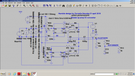
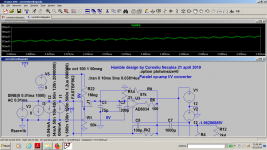
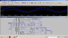
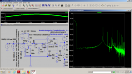
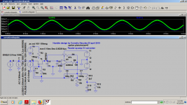
There's a first version described and built for a Philips cd610 mentioned in the first post which sounds fine , it has no filters built in, i just used some mpx filters from radios and rc first order passive filtering after that.For that i mentioned the advantage of larger drive capability for passive filters with using op-amps in parallel .
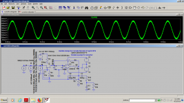
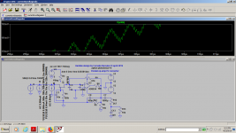
For this version, I have posted complex input with sine modulating two different square wave signals , but the distortions at 1khz aren't affected by the existence of those filters.Those filters of mine aren't working on output current of the dac, they are buffered and i saw that i don't need too large values to filter those high frequencies square wave signals i've put in the sim.
I used Chris suggestion of generating the dac output impedance too...It doesn't really matter if i use his signal model or my model, the difference is barely 10db, while the transistor bias gives up to 50...80 db difference.
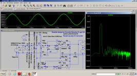
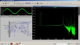
It just takes 10x times more time to sim with a complex input and i can only assess the effectiveness of the filter in wiping out those fast edges.In most cases the sim doesn't show any ringing at all below 1meg, i wasn't curious to investigate the filter as i was more curious of how thd relates to the transistor bias and the base noise level is completely unrealistic, it's like the only player would be the Johnson noise in resistors...
That is why i emphasized at some point somewhere that it's weird that the only transistors that works at modelling with are bc337/bc327 and i tried pretty much all the low noise transistors, even way superior transistors than the bc337. With any other transistor the sim is a complete failure.I actually told Chris that there must be something wrong about the bc337 noise modeling in its own topics.The results are too low.
The only good thing i know is that the circuit works well in its unfiltered version, has a lot of potential and drive and the new added filter inside the feedback loop can be further tinkered in the real world.Every single player or dac would have its own needs for filtering , no two dacs would give the same high frequency content.
I could copy the Abraxalito filters and try with that, but i don't even know what is really there to filter...I just made gross assumptions.
Now the real purpose is to use very low slew rate op-amps but also very low noise , very high CMRR and PSRR and see if it works, that is why i'm building something based on two opa4227, just as a proof of concept.
Attachments
Last edited:
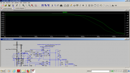
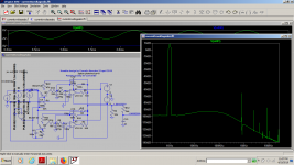
just investigating a bit further...
Attachments
-
 ivact10.png83.4 KB · Views: 81
 -
 ivact9.png80.6 KB · Views: 74
 -
 ivact8.png78.1 KB · Views: 79
 -
 ivact7.png77.9 KB · Views: 75
 -
 ivact6.png86 KB · Views: 84
 -
 ivact5.png90.2 KB · Views: 84
 -
 ivact4.png75.3 KB · Views: 83
 -
 ivact3.png73.2 KB · Views: 226
 -
 ivact2.png70.5 KB · Views: 236
 -
 ivact.png85.7 KB · Views: 236
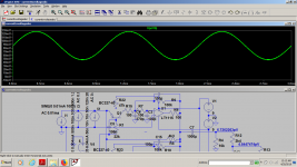
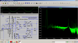
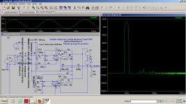
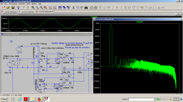
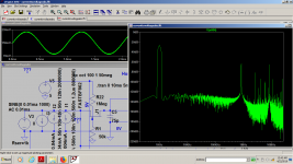
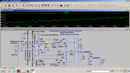
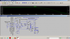
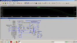
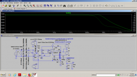
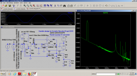
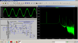
Also some investigations with lower input(some photos in the previous post too), higher freq(10khz) and a bit more agressive filter.I wonder how capable are my ears to hear a less perfect filter.
Attachments
Last edited:
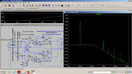
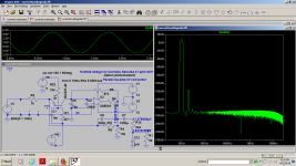
I tried some of your filters inside my circuit and for some reason LtSpice is refusing to show me a clear waveform, but LtSpice is doing the same with all sorts of filters...On Bode plot i can see just that they are very aggressive filters , cutting anything over 20 khz, and the phase response has also a very sharp evolution.Having just scrolled up a bit, if you're putting in a filter inspired by me do your best to have decent damping - that ~1MHz high Q resonance looks potentially problematic. Oh and also I put my filters prior to any active circuitry (including discrete transistors).
I have a very hard time trying to make Lt Spice even to work on some filters...and anyway there are lots of things working very bad while Spice would say it's ok and viceversa, things that LtSpice is refusing completely to sim that wors very well...I'm just following my instincts, but indeed, in pretty much all my filters Spice shows all sorts of resonances btw 100k...1 megahertz.the only worrying thing to me is that the noise looks to be too low in most instances .
Last edited:
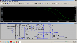
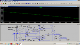
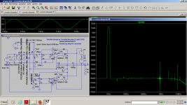
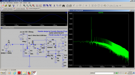
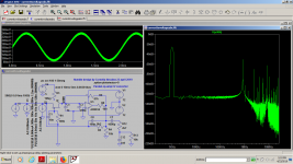
Well....today i went into fet transistors and fet op-amps and i had a huge surprise, i mean, i didn't need complex filters to get everything right:
Attachments
-
 ivfet9.png84 KB · Views: 75
 -
 ivfet8.png98.2 KB · Views: 75
 -
 ivfet7.png66.7 KB · Views: 74
 -
 ivfet6.png86.7 KB · Views: 75
 -
 ivfet5.png79.3 KB · Views: 77
 -
 ivfetx.png76.1 KB · Views: 72
 -
 ivfet4.png70.9 KB · Views: 70
 -
 ivfet3.png86.9 KB · Views: 74
 -
 ivfet2.png70.3 KB · Views: 81
 -
 ivfet.png86 KB · Views: 88
to be continued:
Attachments
-
 ivfet16.png95.3 KB · Views: 73
 -
 ivfet17.png76.9 KB · Views: 71
 -
 ivfet19.png75.4 KB · Views: 72
 -
 ivfet20.png90.7 KB · Views: 77
 -
 ivfet15.png77.1 KB · Views: 65
 -
 ivfet14.png87.8 KB · Views: 63
 -
 ivfet13.png89.4 KB · Views: 67
 -
 ivfet12.png87.3 KB · Views: 66
 -
 ivfet11.png84.2 KB · Views: 74
 -
 ivfet10.png74.3 KB · Views: 73
and again...
Attachments
-
 ivfet27.png79.7 KB · Views: 66
 -
 ivfet28.png88.5 KB · Views: 75
 -
 ivfet29.png88.9 KB · Views: 74
 -
 ivfet30.png88.7 KB · Views: 81
 -
 ivfet26.png95.5 KB · Views: 68
 -
 ivfet25.png85.9 KB · Views: 73
 -
 ivfet24.png82.8 KB · Views: 72
 -
 ivfet23.png82.1 KB · Views: 65
 -
 ivfet22.png68.4 KB · Views: 69
 -
 ivfet21.png69 KB · Views: 77
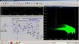
And the last pictures are before the last rc filter and after...a simple order one filter cleans it all after the fet i/v stage.
Next embodiment will be balanced.
Next embodiment will be balanced.
Attachments
I found the answer about the bjt transistor bias and you have some sims showing that you can get lower thd with external bias, but that requires some dc offset that will limit the max output vs rails so the fet version is clearly superior, not to mention that the current noise vs trz hfe might cause some problems unless we need some noise 🙂 The fet noise might be also very obvious at lower currents but i thought of givind it a try as i'm a bit bored by all these simulations...
I also investigated the capability of removing the switching or digital noise and it apears that the circuit can do it very well at 0.01ma input.I couldn't sim with 1ma input though for some reason(probably the dc offset is too high with the values i've chosen)...but now i have the fet versions which i found cooler!
I also investigated the capability of removing the switching or digital noise and it apears that the circuit can do it very well at 0.01ma input.I couldn't sim with 1ma input though for some reason(probably the dc offset is too high with the values i've chosen)...but now i have the fet versions which i found cooler!
Attachments
-
 ivbiasbjtfet10.png85.7 KB · Views: 85
 -
 ivbiasbjtfet9.png72.5 KB · Views: 74
 -
 ivbiasbjtfet8.png70.5 KB · Views: 76
 -
 ivbiasbjtfet7.png70.9 KB · Views: 73
 -
 ivbiasbjtfet6.png76.3 KB · Views: 68
 -
 ivbiasbjtfet5.png76.9 KB · Views: 74
 -
 ivbiasbjtfet4.png91.6 KB · Views: 78
 -
 ivbiasbjtfet3.png92.6 KB · Views: 81
 -
 ivbiasbjtfet2.png95.7 KB · Views: 81
 -
 ivbiasbjtfet.png94.1 KB · Views: 102
Last edited:
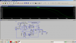
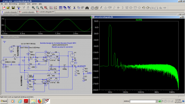
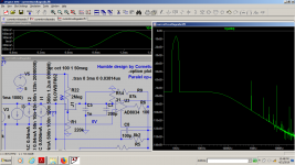
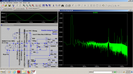
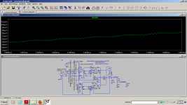
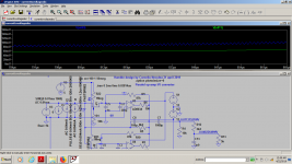
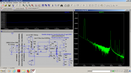
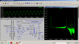
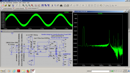
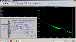
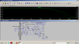
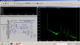
Today i tried a 10khz signal just to see how affected is the audio band and after that i came back at 1khz with complex input .You have both unfiltered and filtered signals and their thd's...In the last sims i removed one bias resistor that usually give me 10db more headroom at 1khz...than got it back again at 10khz
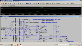
I randomly chose u309out of the spice library but most of the fet transistors give the same results because the op-amp is taking care of any problem.The last sims are with the same bf862
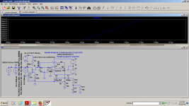
Today i'm building this fet version with 2sk117 as its noise is best at 0.5ma which means that 2 sections in parallel will equal the 1ma max output of the PCM1701...
I randomly chose u309out of the spice library but most of the fet transistors give the same results because the op-amp is taking care of any problem.The last sims are with the same bf862
Today i'm building this fet version with 2sk117 as its noise is best at 0.5ma which means that 2 sections in parallel will equal the 1ma max output of the PCM1701...
Attachments


to be continued...
Attachments
-
 iv1k13.png88.3 KB · Views: 67
 -
 iv10k5.png81.7 KB · Views: 64
 -
 iv10k6.png73.1 KB · Views: 70
 -
 iv10k7.png92.5 KB · Views: 67
 -
 iv1k12.png77.8 KB · Views: 67
 -
 iv1k11.png83.7 KB · Views: 70
 -
 iv1k10.png92.4 KB · Views: 68
 -
 iv1k9.png84.7 KB · Views: 75
 -
 iv1k8.png67 KB · Views: 76
 -
 iv1k7.png76.6 KB · Views: 81
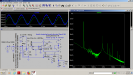
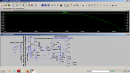

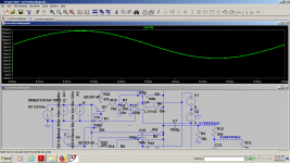
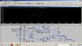
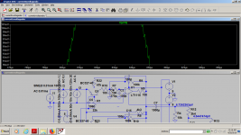
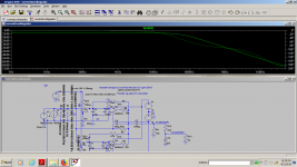
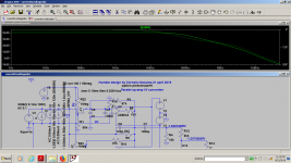
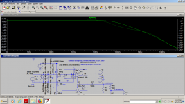
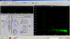
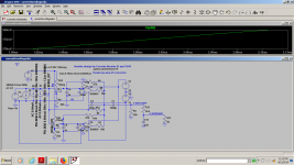
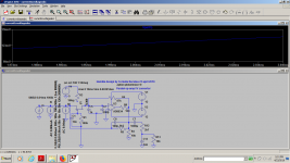
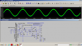
I want to be hones: I am not looking forward to deciphering several dozen pictures without any comments to what is what.
That may be one reason why reactions are lukewarm.
Jan
That may be one reason why reactions are lukewarm.
Jan
Well Sir...Thank you for your kind comments!
A while ago i asked the all mighty Gods of Diyaudio to help me in debunking this i/v idea here:
I/V mod-nelp needed
It seems that i enjoy doing it all alone for my own pleasure 🙂
A while ago i asked the all mighty Gods of Diyaudio to help me in debunking this i/v idea here:
I/V mod-nelp needed
It seems that i enjoy doing it all alone for my own pleasure 🙂
Last edited:
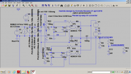
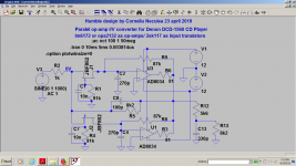
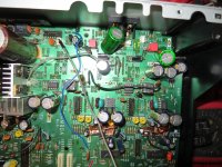
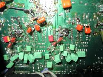
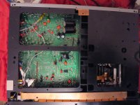
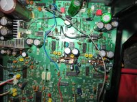
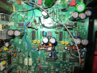
After so much time i got to mod my Denon DCD-1560 adding the fet version of my i/v stage .I used 2sk117 and a few different op-amps like lm6172, opa2132 and njm2043.I'm still evaluating the circuit.
Dynamics and fragrance still depends on the op-amps, as i didn't modify the original filters , only buffering the 270pf capacitor at the dac output and giving the dac a more liniar load to deal with.
With OPA2132 the base is very deep...really deep, i almost don't care about the highs with it, still enjoying it.I'd probably look for a faster fet op-amp in the future, as the one in the simulation.Lm6172 i feel is a bit on the bright side.Next step is evaluating different filters and introducing the new bjt buffered monster you're going to see the next time.With this player op2132 sounds actually better than lm6172...than it does the same job in the Sony cdp-750 based on tda1541...I think that the -4x less current given by pcm1701 is the source of why opa2132 is better in this position.Lm6172 is better suited for higher output dacs.
And it's all so silent .Unfortunately i can't really remember well the previous sound as i didn't listen for about 1 year to this player but i did lots of mods on this player in the last 3 weeks and i can hardly say who's the real culprit for such a good sound that i can't believe.
All in all, I'm HAPPY!
Attachments

Last edited:
It seems that i enjoy doing it all alone for my own pleasure 🙂
The true spirit of diy audio! 😎
Jan
Yes..it is indeed...When i started audio i thought that i'd do some money out of it...I soon realized that spending money will be the main occupation around audio so, if i can't sell a damn thing at least i should enjoy it 🙂
Now honestly i literally feel like crying listening to this player.I should...but i can't...and i don't have a wife around me to do it for me. I think that this is the best i can get and i can't say that i didn't listen to much more modern pieces of audio technology.
Now honestly i literally feel like crying listening to this player.I should...but i can't...and i don't have a wife around me to do it for me. I think that this is the best i can get and i can't say that i didn't listen to much more modern pieces of audio technology.
Last edited:
- Status
- Not open for further replies.
- Home
- Source & Line
- Digital Source
- New i/v stage in town