"PRACTICAL IMPLEMENTATIONS OF ALTERNATIVE POST-DAC FILTERING"
Introduction:
This thread represents many hours of preparation and the information it contains is intended to be of practical use for DIY'ers of various levels of experience, to have some fun and hopefully hear a nice improvement.
What is proposed here is not as radical as some may think. Many of us are familiar with RIAA and NAB EQ etc, where we have a non-standard frequency response somewhere in the chain, which is then corrected for elsewhere in the chain. Here the change is relatively mild, so mild in fact that it is up to the individual whether even to correct for it.
This topic applies to delta-sigma DACs and varying the response in the top octave and a bit - that it has been observed that it has a sonic benefit, whether or not it is corrected for, whether or not EQ is applied.
IMPORTANT: It has no effect on Ladder DACs or NOS-DACs, only delta-sigma types.
Why is this sound change observed? That is admittedly not yet entirely understood, but we are working on it and we feel that some progress has been made and there are certainly ideas as to why. But the observation has been made by a number now in the hundreds that there is a benefit to this approach. So while we are looking to present hard data in the future, there is no need to hold back from enjoying the benefits right now.
"The solution is not the answer, but the question." Niels Bohr
Based on a number of experiments with different delta-sigma DACs, this is the response 'on the pins' of the DAC's output that has proved successful and suggested to aim at:
This is actually a First Order filter curve - it is not difficult to EQ, if that is desired.
Various ways of exploring EQ and to return that response to 'flatness' will be presented. In some cases it can be explored by the first following stage, where the DAC's output has been buffered (Scenario One will be the prime example of this), but in other cases this is impractical, but if you are using a Music Server like JRiver, then you can EQ it from there before it even gets to the DAC. We shall present quite precise information how that can be done. So have some fun and you may be surprised at the result.
-----
Scenario One:
"Current" DAC into Opamp I/V (Most common "current" I/V - EQ possible.)
Arguably, this is the most important one. It represents the most common "current" DAC circuit.
The original suggested schematic for Burr-Brown PCM1794A looks like this:
This will work with most "current" DACs out there. The values may be different and also, while the VRef here is Grounded, even when VRef is set above ground, other DACs from Analog Devices etc can be used. This is because the added post-DAC filter components will be floating.
But take the above example, this is where it gets interesting:

Note, no components were removed, only passive components added.
The 2 x 3R3 and 1uF form the new post-DAC filter added. The 2 x 12nF caps can be finely tweaked to restore response to 'flatness' - the point here is that the response directly impinged on the DAC has a beneficial function.
Let's take a look at the different responses of the post-DAC circuit, all three possibilities are presented:

Blue is what triggers the effect we want.
Green is the original response before any changes.
Red is the final response when both the new post-DAC filter and EQ has been applied.
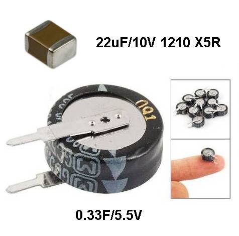
The only other thing to mention, parts are easily sourced, even the 0.33F/5.5V is available from eBay for about $1.
The financial cost of doing the above, is probably less than $10.
Does it work? I think many of you will be in for a nice surprise.
End of Scenario One.
Introduction:
This thread represents many hours of preparation and the information it contains is intended to be of practical use for DIY'ers of various levels of experience, to have some fun and hopefully hear a nice improvement.
What is proposed here is not as radical as some may think. Many of us are familiar with RIAA and NAB EQ etc, where we have a non-standard frequency response somewhere in the chain, which is then corrected for elsewhere in the chain. Here the change is relatively mild, so mild in fact that it is up to the individual whether even to correct for it.
This topic applies to delta-sigma DACs and varying the response in the top octave and a bit - that it has been observed that it has a sonic benefit, whether or not it is corrected for, whether or not EQ is applied.
IMPORTANT: It has no effect on Ladder DACs or NOS-DACs, only delta-sigma types.
Why is this sound change observed? That is admittedly not yet entirely understood, but we are working on it and we feel that some progress has been made and there are certainly ideas as to why. But the observation has been made by a number now in the hundreds that there is a benefit to this approach. So while we are looking to present hard data in the future, there is no need to hold back from enjoying the benefits right now.
"The solution is not the answer, but the question." Niels Bohr
Based on a number of experiments with different delta-sigma DACs, this is the response 'on the pins' of the DAC's output that has proved successful and suggested to aim at:
This is actually a First Order filter curve - it is not difficult to EQ, if that is desired.
Various ways of exploring EQ and to return that response to 'flatness' will be presented. In some cases it can be explored by the first following stage, where the DAC's output has been buffered (Scenario One will be the prime example of this), but in other cases this is impractical, but if you are using a Music Server like JRiver, then you can EQ it from there before it even gets to the DAC. We shall present quite precise information how that can be done. So have some fun and you may be surprised at the result.
-----
Scenario One:
"Current" DAC into Opamp I/V (Most common "current" I/V - EQ possible.)
Arguably, this is the most important one. It represents the most common "current" DAC circuit.
The original suggested schematic for Burr-Brown PCM1794A looks like this:
This will work with most "current" DACs out there. The values may be different and also, while the VRef here is Grounded, even when VRef is set above ground, other DACs from Analog Devices etc can be used. This is because the added post-DAC filter components will be floating.
But take the above example, this is where it gets interesting:
Note, no components were removed, only passive components added.
The 2 x 3R3 and 1uF form the new post-DAC filter added. The 2 x 12nF caps can be finely tweaked to restore response to 'flatness' - the point here is that the response directly impinged on the DAC has a beneficial function.
Let's take a look at the different responses of the post-DAC circuit, all three possibilities are presented:
Blue is what triggers the effect we want.
Green is the original response before any changes.
Red is the final response when both the new post-DAC filter and EQ has been applied.
The only other thing to mention, parts are easily sourced, even the 0.33F/5.5V is available from eBay for about $1.
The financial cost of doing the above, is probably less than $10.
Does it work? I think many of you will be in for a nice surprise.
End of Scenario One.
Last edited:
Scenario Two:
"Voltage" DAC into Single/Summing Opamp. (No EQ possible except JRiver.)
It is only logical that we now look at the most common type of circuit for "voltage" DACs.
These tend to be used in lesser players or DACs, many consider them poor cousins of the "current" family. Yet some manufacturers take a different view and only make "voltage" DACs. These are Cirrus Logic, Wolfson and AKM etc. So even "voltage" DACs are a serious matter.
The difficulty here is that with "current" DACs in Scenario One, we know the termination impedance is always going to see a nominal zero Ohm (called Virtual Ground) and hence the component value for the new post-DAC filter is always going to be the same, they are locked in (3R3 & 1uF). But with "voltage" DACS, things are not so easy to predict.
So with "voltage" DAC implementations, values are less predictable, some tweaking of values is going to be required.
Here is a very conventional circuit:

Here are the recommended changes:

It is much more difficult to EQ this than Scenario One (there is no inter-stage to buffer EQ). My inclination is not to bother, but it may bother others. If you are feeding the DAC from a Music Server like JRiver (which is the Media Centre I recommend) and its 64 bit Parametric EQ, then you have your solution, and indeed this offers a chance to listen and compare what the post-DAC EQ does, by simply turning it 'on' and 'off'. This can be explored and reported back, whatever your experience may be.
JRiver settings will also be made available here in Post #6, so please read on.
_________________________________
Scenario Three:
Scenario Three: into Balanced Opamp Circuit. (Easiest opamp solution for 'voltage" DAC? - EQ may be possible.)
There will be instances where the post-DAC "voltage" will look like this:

The reason for this circuit arrangement is to provide an additional balanced output (XLR) and a summing stage for the unbalanced output (RCA).
This may be explored in order to find an EQ method. But the EQ, if possible, will likely only work for the unbalanced (RCA) outputs.

I did model this in SoundEasy and this particular example can be EQ'd. Make C = 33nF and tweak to get our target roll-off curve, then delete the two 3.3nF that are circled - then the curve will become flat again. But only on the final unbalanced output (the balanced output needs JRiver or a server that can EQ).
But every situation can and will be different, so what works in this instance may not always.
Again, if using a Media Server like JRiver, then you have other options. See Post #6.
End of Scenarios Two and Three.
"Voltage" DAC into Single/Summing Opamp. (No EQ possible except JRiver.)
It is only logical that we now look at the most common type of circuit for "voltage" DACs.
These tend to be used in lesser players or DACs, many consider them poor cousins of the "current" family. Yet some manufacturers take a different view and only make "voltage" DACs. These are Cirrus Logic, Wolfson and AKM etc. So even "voltage" DACs are a serious matter.
The difficulty here is that with "current" DACs in Scenario One, we know the termination impedance is always going to see a nominal zero Ohm (called Virtual Ground) and hence the component value for the new post-DAC filter is always going to be the same, they are locked in (3R3 & 1uF). But with "voltage" DACS, things are not so easy to predict.
So with "voltage" DAC implementations, values are less predictable, some tweaking of values is going to be required.
Here is a very conventional circuit:
Here are the recommended changes:
It is much more difficult to EQ this than Scenario One (there is no inter-stage to buffer EQ). My inclination is not to bother, but it may bother others. If you are feeding the DAC from a Music Server like JRiver (which is the Media Centre I recommend) and its 64 bit Parametric EQ, then you have your solution, and indeed this offers a chance to listen and compare what the post-DAC EQ does, by simply turning it 'on' and 'off'. This can be explored and reported back, whatever your experience may be.
JRiver settings will also be made available here in Post #6, so please read on.
_________________________________
Scenario Three:
Scenario Three: into Balanced Opamp Circuit. (Easiest opamp solution for 'voltage" DAC? - EQ may be possible.)
There will be instances where the post-DAC "voltage" will look like this:
The reason for this circuit arrangement is to provide an additional balanced output (XLR) and a summing stage for the unbalanced output (RCA).
This may be explored in order to find an EQ method. But the EQ, if possible, will likely only work for the unbalanced (RCA) outputs.
I did model this in SoundEasy and this particular example can be EQ'd. Make C = 33nF and tweak to get our target roll-off curve, then delete the two 3.3nF that are circled - then the curve will become flat again. But only on the final unbalanced output (the balanced output needs JRiver or a server that can EQ).
But every situation can and will be different, so what works in this instance may not always.
Again, if using a Media Server like JRiver, then you have other options. See Post #6.
End of Scenarios Two and Three.
Last edited:
Scenario Four:
"Voltage" DAC into 1:1 Transformer (My Preference for "voltage" DACs, no EQ possible except JRiver.)
My favourite when it comes to all "voltage" DACs. This uses a 1:1 transformer and an 'over-cooked' Zobel network that creates a First Order curve between 1KHz and 20KHz.
The key is the Zobel Network. The "R" 1K5 and "C" 15nF are only a possible example of values.
The goal here is to adjust those "RC" values and achieve a 1st Order filter response by use of an "over-cooked" Zobel network.
The target response is the same as earlier, but repeated here:
The basic understanding here is that "C" affects the response at 10KHz and "R" affects 20KHz. Adjust both till you get the above target for those two frequencies relative to reference at 1KHz.
Indeed, start with "C" 15nF and then adjust "R" 1K5 . Adjust "R" to be -2dB at 20KHz. Then check 10KHz and if it is -0.7dB, then it's fine. If response has not come down to -0.7dB, then increase capacitor value and vice versa. Then adjust "R" again to -2dB and check 10KHz. Keep going back and forward until target has been achieved.
In Post #6 you will see a link with Flac files of 1KHz, 10KHz and 20KHz, to assist you. Play as files via a server or burn to a CD-R if DAC is part of a disk player.
There is no way to implement EQ here, other than JRiver or via Media Centre. But in my case, I am happy to leave it without EQ.
There are various possible transformers out there, from Lundahl and Sowter, but Vigortronix also makes an inexpensive transformer that works surprisingly well.
Look for audio grade transformer, 1:1 and 600R:600R as a guide.
Personally, I love this "voltage" solution above all. No opamps, no power supplies, literally the signal comes from the DAC itself. Even low-cost Cirrus Logic "voltage" DACs sound so good.
NOTE: Fully balanced operation possible, even via a floating RCA output, make RCA to XLR cable. Or simply wire up to XLR sockets.
End of Scenario Four.
Last edited:
Scenario Five:
"Current" DAC into Low Z Passive I/V and OTA. (My favourite for suitable "current" DACs, but EQ problematic except JRiver.)
This is my definite favourite for "current" DACs, but only the variety that have no offset voltages, it must have no DC Offset. So the series of Burr-Brown DAC, both PCM and DSD series, 1792, 1794, 1794A, 1796 & 1798, all qualify.
Oddly enough, it is also suitable for ESS Sabre DACs, ES9016 and ES9018. Although these have a DC Offset, they are different from the others in that they can be pulled to Ground, yes physical Ground. The offset voltage changes to offset current of around 2.1mA per phase. So this is fine.
The circuit shown here is based on OPA860 which is currently available. But for DIY pursposes, I would recommend the obsolete (no longer manufactured) OPA660, which is still available on eBay:

Be sure to adjust output to a max of 2V RMS, in fact just a little less, because the power supply is only -/+5V.
NOTE:This is definitely for the more advanced DIY'ers.
Again, EQ is difficult, is not entirely impossible, but problematic:
Find the correct gain resistor value, R1 and R2 to be the same value, parallel them and add an Inductor of the correct value in series to one of them.
I have used this or variations of it many times, without any EQ. But EQ using JRiver Media Centre is an option when playing non-optical sources.
End of Scenario Five.
"Current" DAC into Low Z Passive I/V and OTA. (My favourite for suitable "current" DACs, but EQ problematic except JRiver.)
This is my definite favourite for "current" DACs, but only the variety that have no offset voltages, it must have no DC Offset. So the series of Burr-Brown DAC, both PCM and DSD series, 1792, 1794, 1794A, 1796 & 1798, all qualify.
Oddly enough, it is also suitable for ESS Sabre DACs, ES9016 and ES9018. Although these have a DC Offset, they are different from the others in that they can be pulled to Ground, yes physical Ground. The offset voltage changes to offset current of around 2.1mA per phase. So this is fine.
The circuit shown here is based on OPA860 which is currently available. But for DIY pursposes, I would recommend the obsolete (no longer manufactured) OPA660, which is still available on eBay:
Be sure to adjust output to a max of 2V RMS, in fact just a little less, because the power supply is only -/+5V.
NOTE:This is definitely for the more advanced DIY'ers.
Again, EQ is difficult, is not entirely impossible, but problematic:
Find the correct gain resistor value, R1 and R2 to be the same value, parallel them and add an Inductor of the correct value in series to one of them.
I have used this or variations of it many times, without any EQ. But EQ using JRiver Media Centre is an option when playing non-optical sources.
End of Scenario Five.
Last edited:
Scenario Six:
"Current" DAC Single-Phase Passive (Very unusual and worth a try, but no EQ possible except JRiver.)
I came across this idea from a commercial stand-alone DAC:

With a bit of minor work and adding our alternative post-DAC filter, it was rather a surprise. Naturally, the Burr-Brown DAC seeing 300R per phase is not datasheet optimum. But as an alternative to getting rid of opamps in the circuit and power supplies etc, it is an example I shall keep in mind.
In fact, if you have a preamp and enough gain in your system, that straight out 400mV will also have a reasonably low output impedance and may have just enough output level. What you effectively have done is convert a "current" DAC into a "voltage" DAC and no active circuitry. I felt it intriguing enough to include it here.
Let's take that another step further:

You can also get balanced output, taken from both phases and an additional coupling cap, you can get 0.8V RMS out via only passive components.
_________________________________
Scenario Seven:
"Current" DAC as used in the past by Coris and by Rick Schultz in his Oppo 95. (Very few parts, good for balanced, but no EQ possible except JRiver.)
This is the classic OPA1632 I/V converter circuit, balanced in and balanced out:
This is a simple balanced option with remarkably few components. It can also be used for unbalanced out (RCA) with the gain set at 2V RMS. The fully balanced output will then be 4V RMS.
As before, with all Virtual Grounds, we can go back and use the original 2 x 3R3 and 1uF values.
This is about the simplest way to get a balanced and unbalanced output with few components.
_________________________________
Scenario Eight:
Sabre DAC ES9018 into 1:1 Transformer.
This is used by some of the Buffalo DAC guys and I thought I should show it here. For this to work at its best, in my opinion, you should have separate ES9018 per channel and ALL eight phases paralleled. The example below shows four phases in parallel from a single stereo ES9018. This will also work with Burr-Brown PCM/DSD 1792, 1794A, 1796 and 1798:
While it says 2V RMS out, that is only a guess and if you use Sabre DAC x 8 phases, then you may need to reduce resistors to 12R and increase C = 0.27uF. As always, check the final response and tweak it to match the required curve/response.
End of Eight Scenarios.
"Current" DAC Single-Phase Passive (Very unusual and worth a try, but no EQ possible except JRiver.)
I came across this idea from a commercial stand-alone DAC:
With a bit of minor work and adding our alternative post-DAC filter, it was rather a surprise. Naturally, the Burr-Brown DAC seeing 300R per phase is not datasheet optimum. But as an alternative to getting rid of opamps in the circuit and power supplies etc, it is an example I shall keep in mind.
In fact, if you have a preamp and enough gain in your system, that straight out 400mV will also have a reasonably low output impedance and may have just enough output level. What you effectively have done is convert a "current" DAC into a "voltage" DAC and no active circuitry. I felt it intriguing enough to include it here.
Let's take that another step further:
You can also get balanced output, taken from both phases and an additional coupling cap, you can get 0.8V RMS out via only passive components.
_________________________________
Scenario Seven:
"Current" DAC as used in the past by Coris and by Rick Schultz in his Oppo 95. (Very few parts, good for balanced, but no EQ possible except JRiver.)
This is the classic OPA1632 I/V converter circuit, balanced in and balanced out:
This is a simple balanced option with remarkably few components. It can also be used for unbalanced out (RCA) with the gain set at 2V RMS. The fully balanced output will then be 4V RMS.
As before, with all Virtual Grounds, we can go back and use the original 2 x 3R3 and 1uF values.
This is about the simplest way to get a balanced and unbalanced output with few components.
_________________________________
Scenario Eight:
Sabre DAC ES9018 into 1:1 Transformer.
This is used by some of the Buffalo DAC guys and I thought I should show it here. For this to work at its best, in my opinion, you should have separate ES9018 per channel and ALL eight phases paralleled. The example below shows four phases in parallel from a single stereo ES9018. This will also work with Burr-Brown PCM/DSD 1792, 1794A, 1796 and 1798:
While it says 2V RMS out, that is only a guess and if you use Sabre DAC x 8 phases, then you may need to reduce resistors to 12R and increase C = 0.27uF. As always, check the final response and tweak it to match the required curve/response.
End of Eight Scenarios.
Last edited:
JRiver Media Centre and Parametric EQ:
If you run your music through a Media Centre like JRiver, you have instant and flexible EQ available. It is also great for comparing what the EQ does, what it sounds like corrected and uncorrected. If you like in uncorrected, then so much the easier it will be. I personally like it uncorrected - to me a delta-sigma DAC actually sounds flatter when left uncorrected. Note also that moving loudspeakers, even just toeing them in a little more, can easily make up for 2dB lost at 20KHz. Indeed, toeing in speakers should only be done by ear.
Here are the recommended Settings in JRiver:
1. Access DSP Studio
2. Selected "Parametric Equalizer" (note this is also where you can turn in 'on' and 'off')
3. Select Add... Adjust high frequencies (high-shelf filter)
4. Enter parameters:
Frequency: 20000 Hertz (20KHz)
Bandwidth (Q): 0.1
Gain: 4dB
Channels: Left; Right
Clip protection: 'on'
Screen Shot:
The only one you may need to tweak is the 4dB Gain. In my case, with my Oppo 105, I set it to 5 and get the flattest response.
Note, you will get half the Gain at the Frequency you have entered, so 4dB is actually 2dB.
Test Files:
You can download a Zip file, click this link:
Test-Tracks.zip
Unzip and you will have six Flac Files:
The first three tracks are for adjusting post-DAC filter, the last three are for adjusting the JRiver EQ. These last three files are the same, but at -10dBFS (FS means Full Scale and -10dB means 10dB below Full Scale), or else you cannot adjust EQ with a positive value (4 to 5dB) without clipping while trying to adjust. It will drive you mad otherwise.
If you have an oscilloscope, look at these three screen shots, the first is the 1KHz reference, see how 10KHz and 20KHz are rolled off and less amplitude. Copy visually what to see on your scope to match that, and you will be surprisingly close to your target.
1KHz:
10KHz:

20KHz:
So those above is what it should look like uncorrected using FS (full scale files).
When correcting (EQ), use the 'minus' 10dBFS files and make them all look the same as the 1st 1KHz sample.
If in doubt, don't worry, just ask questions as the thread unfolds and you will find guidance.
That's it - take your time in absorbing the above. You can always ask questions and we can all share in whatever we find in our experiences.
I do believe many of you will be surprised at the results I believe you will hear. If you look above, you will see that all we are doing is really just using passive components, not active ones, to achieve our goal.
One last thing, I know it will come up, that 0.33F/5.5V SuperCap. There are so many variations of DACs out there that it would be impossible to discuss them all. Some DACs only have two power supply pins (like many Burr-Brown), one Digital and the other Analog. Other DACs have three or more. It will be up to you to find them and fit a typical 22uF/10V SMD ceramic cap and 0.33F SuperCap in parallel (network). None of these supplies will be more than 5V and often less. Why fit them? Because they get the best out of the new post-DAC filter you have just fitted. I could add more to that and perhaps later will.
Now it's my turn to take a back seat and let you guys get on with it. I can't wait for the feedback.
Also, help each other out, this is not a one-man show, there is LOTS of potential DIY stuff to be done here - those with lesser skills can team up with those who are more confident, and so on.
This is only the beginning... finally.
LET US HAVE A FRIENDLY EXPERIENCE.
NO QUESTION WILL BE CONSIDERED STUPID BECAUSE NO QUESTION IS STUPID TO THE PERSON ASKING.
EVERYBODY SHOULD FEEL WELCOME AND AT HOME HERE.
Cheers, Joe
-
If you run your music through a Media Centre like JRiver, you have instant and flexible EQ available. It is also great for comparing what the EQ does, what it sounds like corrected and uncorrected. If you like in uncorrected, then so much the easier it will be. I personally like it uncorrected - to me a delta-sigma DAC actually sounds flatter when left uncorrected. Note also that moving loudspeakers, even just toeing them in a little more, can easily make up for 2dB lost at 20KHz. Indeed, toeing in speakers should only be done by ear.
Here are the recommended Settings in JRiver:
1. Access DSP Studio
2. Selected "Parametric Equalizer" (note this is also where you can turn in 'on' and 'off')
3. Select Add... Adjust high frequencies (high-shelf filter)
4. Enter parameters:
Frequency: 20000 Hertz (20KHz)
Bandwidth (Q): 0.1
Gain: 4dB
Channels: Left; Right
Clip protection: 'on'
Screen Shot:
The only one you may need to tweak is the 4dB Gain. In my case, with my Oppo 105, I set it to 5 and get the flattest response.
Note, you will get half the Gain at the Frequency you have entered, so 4dB is actually 2dB.
Test Files:
You can download a Zip file, click this link:
Test-Tracks.zip
Unzip and you will have six Flac Files:
The first three tracks are for adjusting post-DAC filter, the last three are for adjusting the JRiver EQ. These last three files are the same, but at -10dBFS (FS means Full Scale and -10dB means 10dB below Full Scale), or else you cannot adjust EQ with a positive value (4 to 5dB) without clipping while trying to adjust. It will drive you mad otherwise.
If you have an oscilloscope, look at these three screen shots, the first is the 1KHz reference, see how 10KHz and 20KHz are rolled off and less amplitude. Copy visually what to see on your scope to match that, and you will be surprisingly close to your target.
1KHz:
10KHz:
20KHz:
So those above is what it should look like uncorrected using FS (full scale files).
When correcting (EQ), use the 'minus' 10dBFS files and make them all look the same as the 1st 1KHz sample.
If in doubt, don't worry, just ask questions as the thread unfolds and you will find guidance.
That's it - take your time in absorbing the above. You can always ask questions and we can all share in whatever we find in our experiences.
I do believe many of you will be surprised at the results I believe you will hear. If you look above, you will see that all we are doing is really just using passive components, not active ones, to achieve our goal.
One last thing, I know it will come up, that 0.33F/5.5V SuperCap. There are so many variations of DACs out there that it would be impossible to discuss them all. Some DACs only have two power supply pins (like many Burr-Brown), one Digital and the other Analog. Other DACs have three or more. It will be up to you to find them and fit a typical 22uF/10V SMD ceramic cap and 0.33F SuperCap in parallel (network). None of these supplies will be more than 5V and often less. Why fit them? Because they get the best out of the new post-DAC filter you have just fitted. I could add more to that and perhaps later will.
Now it's my turn to take a back seat and let you guys get on with it. I can't wait for the feedback.
Also, help each other out, this is not a one-man show, there is LOTS of potential DIY stuff to be done here - those with lesser skills can team up with those who are more confident, and so on.
This is only the beginning... finally.
LET US HAVE A FRIENDLY EXPERIENCE.
NO QUESTION WILL BE CONSIDERED STUPID BECAUSE NO QUESTION IS STUPID TO THE PERSON ASKING.
EVERYBODY SHOULD FEEL WELCOME AND AT HOME HERE.
Cheers, Joe
-
Last edited:
Hi Joe.
Well done summary and schematic examples.
So, you are advocating two ideas here....
1 - Additions of 22uF 10V and 0.33F 5.5V pair across device supply pins.
2 - Addition of capacitor directly across DAC balanced output pins in order to cause audio output with drooping response of -0.7dB at 10kHz, and -2.0dB at 20kHz.
Can you give subjective description of the effects of 1 and 2, and the combined effect please.
Dan.
.
Can you give subjective description of the effects of 1 and 2, and the combined effect please.
Dan.
Hi Dan
Pretty well summed up.
I don't want to overplay the sonic benefits as I would like others to describe it first. Just let me say what others have said, that it is very obvious from the very moment they hear it.
The benefit is similar to reducing jitter via improved clocking and so on. It leads me to think we are seeing a reduction in noise getting into the DAC at the critical moment, the most vulnerable moment, when digital content gets turn into an analog signal. Noise at that point is jitter.
The real test is when people will start reporting back what they will be hearing - I can tell you from past experiences in the last two years, they will hear something that makes digital sound a lot more like analog.
Cheers, Joe
-
An addendum first about scenario 7: if you tie vcom to gnd, then the outputs are held at 0V but the inputs might now be held at some voltage (defined by the current out offset and the value of the I/V resistor). It can lead to distortion with some DACs (in particular the pcm1794 and similar) as the outputs won't be in their proper operating voltage range anymore. The proper way to do it is either to feed vcom with a bias voltage or even to add a servo to keep the inputs of the opa1632 at 0V. In either case, a further stage is required to get rid of the DC offset (or output caps must be added).
And a question about scenario 1, 5, 6, 7 and 8: isn't the output lpf ill defined since it will depend on the output impedance of a particular current out DAC combined with that added cap ? Shouldn't this be tailored for each DAC model ? Even in scenario 2 and 3, the additionnal resistors only mitigate the problem; the DAC output cannot be assumed to have no output impedance. How did you get at the values suggested in each scenario ? Measurements of the low pass filter in circuit ?
And a question about scenario 1, 5, 6, 7 and 8: isn't the output lpf ill defined since it will depend on the output impedance of a particular current out DAC combined with that added cap ? Shouldn't this be tailored for each DAC model ? Even in scenario 2 and 3, the additionnal resistors only mitigate the problem; the DAC output cannot be assumed to have no output impedance. How did you get at the values suggested in each scenario ? Measurements of the low pass filter in circuit ?
The big question, of course, is why would such a small change at the top of the frequency band result in a distinct audible change? I can't hear up that high and am willing to bet most of us here can't either.
How would this small change in the top octave fold down into an area where we can easily notice it?
How would this small change in the top octave fold down into an area where we can easily notice it?
Pano, keep in mind that you have 2 hearing systems, the one commonly measured is in the frequency domain and as we age high frequency falls off, the other system is time based, does not fall off as quickly with age, and is capable of higher resolution (Kuncher shows 5 uS).
dave
dave
The big question, of course, is why would such a small change at the top of the frequency band result in a distinct audible change?
The audibility has not yet been shown. And if it is audible, the next question would be why this would be any different than putting in a little EQ anywhere along the signal chain, including the tweeter feed.
Interchannel phase difference sensitivity is irrelevant if both channels have the same EQ.
But single channel envelope timing may well be.
So might orientation with respect to magnetic north. There's that "evidence" thing missing, though.
I've done a lot of testing of my own hearing in the top octave, much of it pre DAC EQ. I cannot hear the difference between no low pass and 4th order at ~14KHz. I really cannot.
But I do hear a difference with bandwidth limited DACs. Why, I don't know, but I do hear it. Transformer coupled is even a bigger difference. I suspect common mode noise rejection there. Yes, I've done blind tests.
If this little tweak is really audible, then why? It would be nice for someone with wide bandwidth measurements to see if there is HF harsh getting out of the DAC and into the following stages. Or a maybe a simple measurement at the speakers terminals will show a difference. If there is a change, we should be able to see it there.
It will be nice if a few people do this tweak and can show us, by measurement, what they hear. Failing that, it would take a good blind listening test to establish what is going on.
It will be nice if a few people do this tweak and can show us, by measurement, what they hear. Failing that, it would take a good blind listening test to establish what is going on.
Precisely. And to demonstrate a difference between doing EQ in one place or doing it in another.
Yes, that's the main part of the idea, I think. It's not what's going into the DAC, it's what is coming out. Maybe. 🙂
foobar2000 + iZotope RX-3 Hum Removal
Hi to ALL
As I have said many times, I have a main with a lot of noise and continuous. As I have been cleaning come to a similar equalization (LPF) for my ODAC.
At spanish forum, Jul 02, 2015
-> USB Isolator: iFi iUSB vs TeraDak U9VA + Teralink ADuM4160. Filtros Schaffner. Lampizator: AC filter DIY ESA SILK. Estabilizador / regulador de tensión / voltaje. Isolation / Balanced transformer. DC Blocker / Blocking. PC SILENCIOSO en Aussar. Vari
Guy Clark - On the Road Live (1979) (Vinyl, xxxxxxxx, Warner Bros) {24-96} [FLAC]
Note: old american masters (and vinyl) have hum -> 60, 120 and 180Hz is enough.
An addendum first about scenario 7:
That was taken straight from the datasheet and post-DAC filter added to illustrate "implementation" of it - the rest is up to you. Coris and Rick Schultz are the guys who have used the OPA1632 and I am sure they were able to get all the things you say sorted, they are very experienced.
But the point is, that the post-DAC filter also works here. Coris has confirmed that.
Cheers, Joe
- Status
- Not open for further replies.
- Home
- Source & Line
- Digital Source
- Practical Implementations of Alternative Post-DAC Filtering