SM5872 - how to easily combine RO & RON and LO & LON for a valve output stage?
Hi all,
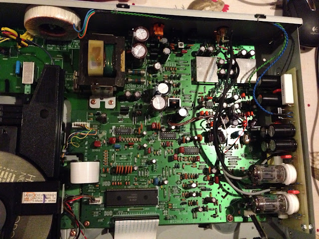
I have a CD63 with SM5872 DAC and with a valve output stage (not added by me) where the output is taken just from LO and RO, ignoring LON and RON.
I've added regulated power supplies to the DAC and updates some caps and such and the sound's great now") Much cleaner and seemingly without horrid digital sounding interference, but there's still an underlying permanent hiss I'd like to get rid of.
Much cleaner and seemingly without horrid digital sounding interference, but there's still an underlying permanent hiss I'd like to get rid of.
Here's a pic:
I've done a lot of reading around after some suggestion that this may be because I'm only using LO and RO and I found some gems from where this has been discussed before like this, but I can't seem to find a simple solution:
Like in this thread:
http://www.diyaudio.com/forums/digi...ose-tube-output-stage-help-appreciated-2.html
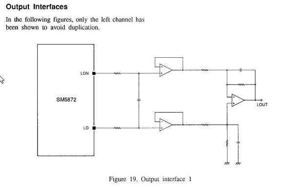
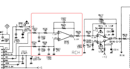
And I've checked the schematics for the DAC and can see a couple of methods for combining the signals to get a correct L-OUT and R-OUT as intended:
And in theory, it looks quite simple But that's where I'm limited by my electronics knowledge..
I would like to achieve this in whatever is the most simple form. I don't need any amplification at this stage, just to combine the signals correctly.
I can follow the layout design for these 2 methods, but I don't have enough knowledge to know which specific types or sizes of components would give me what I need.
Also, I wonder if this is a normal requirement for someone creating a DOS for this DAC and whether there is a standard solution I can use?
Can anyone help me out with advice about how I can achieve this please?
thanks in advance,
James
Hi all,
I have a CD63 with SM5872 DAC and with a valve output stage (not added by me) where the output is taken just from LO and RO, ignoring LON and RON.
I've added regulated power supplies to the DAC and updates some caps and such and the sound's great now
Much cleaner and seemingly without horrid digital sounding interference, but there's still an underlying permanent hiss I'd like to get rid of.Here's a pic:
I've done a lot of reading around after some suggestion that this may be because I'm only using LO and RO and I found some gems from where this has been discussed before like this, but I can't seem to find a simple solution:
Like in this thread:
http://www.diyaudio.com/forums/digi...ose-tube-output-stage-help-appreciated-2.html
Only the two outputs together contain the proper output information
The CD1020 has a fancy output muting and switching scheme which is the first thing I pulled out. It also uses the same output filter arrangement (OP-amp in front of the HDAM) as a CD63, which, like most such constructions (including the one in the CD6000!) is inherently flawed because it presents a different impedance to the LO and LON (and RO/RON respectively) outputs, resulting in errors of the filtering characteristics - particulairly at HF, where the impedance on one of the inputs is dictated by how well the OP-amp is capable of working at the SM5872 fundamental PWM frequency, which is 32Fs - 1.4112MHz. Very few OP-amps are well behaved at this frequency, the classic NE and NJM uparts used in these players are NOT one of them.
Things get much better if most of the filtering is done passively, then summed by a real so-called measurement differential amp topology. This requires 3 amps per channel (or 4 if you want differential outputs as well) - the circuit used in the CD63 saves one OP-amp. What puzzles me in the CD6000 schematic is that they just copy-pasted the same thing for both of the signals comprising a differential output, when they could have used the 'propper' arrangement with the same number of parts, and maybe even less parts.
In the CD1020/CD63 there is space for only one double OP-amp per channel so initially i did the same thing as described above - used just the LO and RO outputs. It sounded about right but was surprisingly noisy - so much so you could see the residual on the output with a scope - a lot of HF hash, even when the player was not playing (the DAC gets a digital zero while the player is in stop mode). The idea that these were remains of the noise-shaping and quasi-diff PWM output coding came when i noticed the hash looked exactly the same on both channels. When I switched one channel to the xON output, and summed the outputs using two equal resistors, the hash cancelled itself out! Of course, moving back to the proper 3-OPamp differential arrangement and passive filtering resulted in a noise-free output, because this arrangement subtracts the xON signal from the xO signal. It also alowed me to use a different type of OP-amp for the post-filter part and output part.
And I've checked the schematics for the DAC and can see a couple of methods for combining the signals to get a correct L-OUT and R-OUT as intended:
And in theory, it looks quite simple
But that's where I'm limited by my electronics knowledge.. I would like to achieve this in whatever is the most simple form. I don't need any amplification at this stage, just to combine the signals correctly.
I can follow the layout design for these 2 methods, but I don't have enough knowledge to know which specific types or sizes of components would give me what I need.
Also, I wonder if this is a normal requirement for someone creating a DOS for this DAC and whether there is a standard solution I can use?
Can anyone help me out with advice about how I can achieve this please?
thanks in advance,
James
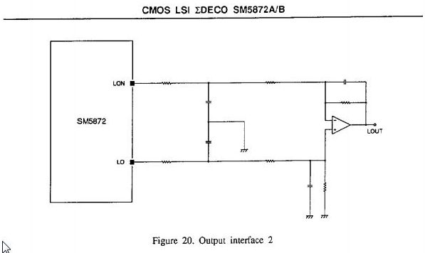
actually, now I look properly, the output interface 2 diagram is basically what the first stage of the dual opamp does in the standard output stage
(just showing 1 channel for simplicity)
So the structure of the circuit I'm after is there already isn't it?
Could anyone recommend which device I could use to create this desired combining of signals which will hopefully cancel out the noise and which will leave the signals at roughly the same overall level? I'm not too worried about matching original pinouts and such if that makes a difference.
I don't mind how it's done if the results are good
cheers,
James
I found in the .HR section here diyaudio.com.hr • Pogledaj temu - Tube bufferi in Croatian where ilimzn was discussing a valve output conversion to an Onkyo DX7310 player which uses the SM5872 DAC.
His proposed solution was to use a 74F175 quad D-type flip-flop thusly:
I can't pretend to understand it fully, but this looks like the type of solution I'm after
His proposed solution was to use a 74F175 quad D-type flip-flop thusly:
I can't pretend to understand it fully, but this looks like the type of solution I'm after
Looks like a lot of the answers are held here
Balanced-Ouput DACs and Tubes and Aikido
Balanced-Ouput DACs and Tubes and Aikido
I would like to achieve this in whatever is the most simple form. I don't need any amplification at this stage, just to combine the signals correctly.
James
taking only positive or negative DAC output is fine.
to utilise full differential DAC out, you have to use differential input stage, tube or OP based, which is an additional stage whatever way you look at it.
the 74F175 based circuit diagram is quite an interesting one! It re-clocks the DAC output bit stream + it properly combines two signals coming out of DAC. It also does correct filtering and conditions the signal before it hits the analog (in your case valve) stage. The correct chip for this circuit is 74AC175 (or 74HC175).
The hiss you hear in your system is not caused by taking a single ended DAC output (referenced to ground) to valve output stage. It is most likely caused by something else...
Boky
- Status
- This old topic is closed. If you want to reopen this topic, contact a moderator using the "Report Post" button.