I bought a JVC XL-Z1050TN CD player that was supposedly modified by Stan Warren for $100. It sounds really good, but on initial start-up, there is noise (like white noise, pink noise) coming through the left channel. This noise goes away after the unit has had time to warm up. I believe one of the electrolytic caps in the out stage PCB might be going bad. Considering that this 20+ year unit probably needs new electrolytic caps anyway, I took a look and identified the following caps in the power supply and output stage boards:
Power Supply:
The green jacketed Nippon Chemi-Con NX-V (or NX-5) caps on the output stage board are a total mystery to me. I initially thought they were Nichicon ES nonpolar caps at first until I looked at them more closely. Here is a photo from this remarkable Lampizator Web site (Lampizator JVC K2 1050 CD Player with XRCD dac) that shows where these green jacketed caps are situated on the output stage board.

From the service manual schematics, they appear to be decoupling caps for the DAC.
Any assistance is greatly appreciated.
Power Supply:
- 2x Nippon Chemi-Con AWF 2200uF/50V
- 1x Nippon Chemi-Con AVF 100uF/50V
- 1x Elna Silmic 100uF/50V
- 2x Nichicon ES 220uF/50V
- 4x Rubycon MBZ 1500uF/16V
- 3x Nippon Chemi-Con NX-V 2200uF/16V
- 1x Nippon Chemi-Con NX-V 100uF/10V
The green jacketed Nippon Chemi-Con NX-V (or NX-5) caps on the output stage board are a total mystery to me. I initially thought they were Nichicon ES nonpolar caps at first until I looked at them more closely. Here is a photo from this remarkable Lampizator Web site (Lampizator JVC K2 1050 CD Player with XRCD dac) that shows where these green jacketed caps are situated on the output stage board.
From the service manual schematics, they appear to be decoupling caps for the DAC.
Any assistance is greatly appreciated.
That is not a typical symptom of cap failure, but it's possible. However, you can completely rule out any chance of the Nichicons being even slightly less than healthy, and it's very unlikely any of the Chemicons are dying either. It is VERY likely that the Elna & Rubycons are on their way out, though. But do yourself a favor & use Nichicons for replacements. Panasonics are as guaranteed to fail within a few years as any brand on earth(save perhaps Nover), being tied for worst cap maker in Japan(if not the world) with Elna(speaking from a reliability standpoint, which is as important to me as performance).
Your noise problem may be hard to track down, considering how short it's duration is. I would start by looking at the output of the dac with a scope at turn on, to see if the noise is before or after the output stage. If it's not coming out the dac, I'd start by going ahead & simply replacing the output stage chip/chips, and see if that cures it. If it persists, then you've got a job to nail down the cause.
Your noise problem may be hard to track down, considering how short it's duration is. I would start by looking at the output of the dac with a scope at turn on, to see if the noise is before or after the output stage. If it's not coming out the dac, I'd start by going ahead & simply replacing the output stage chip/chips, and see if that cures it. If it persists, then you've got a job to nail down the cause.
Thanks Lautar. I will check this out.
Sorry for resurrecting an old thread,
is it possible to share the service manual again?
I'm playing on a XL-Z574 but as far as I can see on Lampizator website, it shares many parts and design with the 1050.
So far I bypassed every elco in the PSU board, added a bigger elco cap for the digital PSU, bypassed rectifying diodes for the analog PSU section, started bypassing elco caps in the digital section.
Mechanically I started adding blutack to the transport unit which seems identical to the 1050 one.
Same approach on a Pioneer DV-300 brought impressive results, at least when used as a transport.
It would be interesting to use SLA batteries for the digital section a-la shigaraki, but I'd need a schematic in order to understand where to wire them... 🙂
Thanks for any hint,
Stefano
Last edited:
XL-Z574 service manual
You've probably found it already, but here is a link to it anyway...
JVC XL-Z574 Service Manual free download,schematics,datasheets,eeprom bins,pcb,repair info for test equipment and electronics
You've probably found it already, but here is a link to it anyway...
JVC XL-Z574 Service Manual free download,schematics,datasheets,eeprom bins,pcb,repair info for test equipment and electronics
Oh great!!! I hadn't yet 🙂
Many thanks, my 574 is reading TOC and seems to play fine from the display but is silent... so I need to discover where I messed with it...
Kind regards to Suomi
Stefano
Many thanks, my 574 is reading TOC and seems to play fine from the display but is silent... so I need to discover where I messed with it...
Kind regards to Suomi
Stefano
Try to read the schematics first, some parts are totally unreadable.
But sure, you're welcome.
I actually paid for that in the first place, wasn't exactly happy when I got the pdf.. 😉
BTW, I got my XL-Z574 from junkyard, just brought it home and checked inside, one fusible resistor had a tiny dark spot so I changed it. Now it works like charm. Pretty nice finding.
But sure, you're welcome.
I actually paid for that in the first place, wasn't exactly happy when I got the pdf.. 😉
BTW, I got my XL-Z574 from junkyard, just brought it home and checked inside, one fusible resistor had a tiny dark spot so I changed it. Now it works like charm. Pretty nice finding.
Hmm, I'm seeing...
...anyway at least I didn't do any harm by desoldering the 4 output muting transitors. So I'm thinking of desoldering what seem to me 2 more muting transistors for headphones out, too (Q305, Q306).
Since the player behaves as if it's playing regularly, I think that while adding bypass caps, somewhere I put the digital signal to ground before the DAC.
Time to look for it...
BTW this 574 was my second cdp after a Seleco copy of the Sony CDP-101. I bought it new many years ago and is a piece of my family history 😉 I started "messing" with it since it refused to play discs. Some cleaning and modding to the PSU board did wonders. Stage 2 was to attack the main board...
Last edited:
Ahem,
here again. So, I listened with more attention with headphones and was able to hear a test track but at a very very low volume, almost indistinguishable from background (yes, headphones are ok).
What I did is add bypass 400MKT to every elco, desolder muting transistors and bypassing a couple of caps in series to signal for headphones. An inspection with magnifier didn't reveal any short around...
Voltage values between pins 1-4 of the four NE5532 equivalent opamps varies in a [0 - 1.5] range.
TIA for any further advice,
Stefano
Last edited:
As a followup,
thanks to the SM you uploaded, I found that I had shorted to ground the signal by replacing C385 and 386 with jumpers 🙂 I thought they were coupling caps and not LPF caps...
Now, back to the JVC: from the diagram I found a pair of muting transistors for headphones output and some ELCO coupling caps (these should be bypassed with a wire 🙂)
Thank you again!
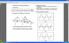
Stefano hi, I had one of the JVC-1010tN and made a considerable improvement to it by disconecting the muting and headphones, then exchange the NE5532's for AD 825' on Browndog adaptor boards, then direct couple the output (short out the coupling cap) then short out two of the three 100ohms series output resistors to make it 100ohm output impedance.
After all that is done adjust the MSB (most significant bit) on both channels, use a good sensitive scope an you won't need the the recommended amp circuit in the diagram. Then it will sing.
Cheers George
After all that is done adjust the MSB (most significant bit) on both channels, use a good sensitive scope an you won't need the the recommended amp circuit in the diagram. Then it will sing.
Cheers George
Attachments
Last edited:
Thank you George for all these advices,
I just spent a couple of hours at listening at the results bynow with a pair of shure earphones (those once recommended by Mr. Linkwitz) and am really satisfied. The headphones sound is so good to me that I don't know if I will be able to disconnect the headphones output...
I saw three resistors just before the output (R346, 347, 348 for one channel) but aren't they marked as 51Ohm? Should I get rid of only one of it? Why are we looking for 100Ohm output impedance (my pre is an Accuphase C222).
Bear with me, George, I looked for R329 and R330 on my schematics. They are after a first op amp, spec'd as 2K. Was the same on yours? And, wouldn't you suggest to upgrade the op-amp output stage to a discrete or tubed one?
Thanks a lot for sharing and for your patience 🙂
Stefano

Thanks a lot George and Ahiukka,
bynow I removed all muting (yet can't hear any nasty sounds), all signal coupling caps and this evening I'm going to evaluate the sound (I still have to fix a jumper not well soldered).
BTW I found empty room for elco caps between opamps. From the somewhat hard to read schemas they seems caps supporting each opamp Vcc (so to say). I'll try to fill them even if not with 100V rated caps as I seem I can read...
Stefano
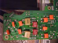
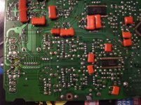
followup
Here are a couple of shots showing the bypass work with caps and/or jumpers, all muting removal and the two rows of caps (rated 10/100 and 4,7/100).
From the schema (last pic) I haven't yet decided what to do with these missing caps (they are designed, yet are not present neither on the part list or on the board): whether solder the specified ELCOs or film caps, or both, or nothing 😛
The sound of the unit - at least via headphones - is now very very good. Indeed I've heard lines and details never heard on well known tracks. But in general there is much more of everything... and I've collected a bunch of re-usable transistors and caps 🙂
Now, I'd like to try a FET output stage for this little wonder of dac. It seems to me it has balanced outputs 😀
Stefano
Attachments
Snipping out caps
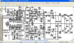
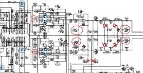
Hi,
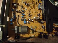
very very old thread, but after moving I found again the unit (a jvc xl-z574) and started playing on it!
Can anybody share his thoughts on the colored caps in the attached picture?
I already removed the "X" marked caps and muting transistor, but was wondering if it would be worth snipping also the remaing red circled ones.
In particular I'm wondering what is the idea behind the shunting (coupling to gnd) of the outputs of the balanced dac inside the unit a MN35502, if I'm correct and if improving the elco caps (maybe xchange with film) between supply pins of the dac may be worth the mess of removing the boarda again!
TIA for any hint,
Hi,
very very old thread, but after moving I found again the unit (a jvc xl-z574) and started playing on it!
Can anybody share his thoughts on the colored caps in the attached picture?
I already removed the "X" marked caps and muting transistor, but was wondering if it would be worth snipping also the remaing red circled ones.
In particular I'm wondering what is the idea behind the shunting (coupling to gnd) of the outputs of the balanced dac inside the unit a MN35502, if I'm correct and if improving the elco caps (maybe xchange with film) between supply pins of the dac may be worth the mess of removing the boarda again!
TIA for any hint,
Attachments
- Status
- Not open for further replies.
- Home
- Source & Line
- Digital Source
- Recap JVC XL-Z1050 CD Player