I try to replace the oscillator inside DVD player. The oscillator is 27Mhz square, 4pad type. I replace it with CTS357, also 27Mhz.
Both are 3V3 supply.
With CTS oscillator, the DVD output picture in the TV has no color, only black and white.
When I put back the original oscillator, the color is back, normal.
I repeat this with another new CTS oscillator then the original oscillator, same result.
I measure the output frequency with frequency counter, the original oscillator is 26.999Mhz while the CTS one is 27.004Mhz.
Is this small difference cause the problem, or there is something else?
The 27MHz oscillator in your DVD player is a straight up crystal oscillator. The CTS357 is a VCXO.
Since the DVD player isn't driving the VCXO control voltage input, the video frequencies generated by your DVD player are hundreds of ppm off frequency. Your television set can't lock onto the offset color carrier, so it's displaying black and white.
No need to bother Elso or Jocko.
Since the DVD player isn't driving the VCXO control voltage input, the video frequencies generated by your DVD player are hundreds of ppm off frequency. Your television set can't lock onto the offset color carrier, so it's displaying black and white.
No need to bother Elso or Jocko.
gmarsh said:
No need to bother Elso or Jocko.
and i suggested this where exactly?
Amasing how people change thing around to feed their egos...
Thanks 
Because I've already got these CTS357 VCXO in my hand, is there any way I can still use them for my modification purpose?
Right now, I put it pin to pin of the original oscillator. Pin 1 and 6 of CTS is connected to VCC, pin 2 and 5=NC, pin 3=GND, and pin4=Output.
What should be connected to pin1 of CTS357 (Control Voltage) so I can make an equivalent of plain crystal oscillator with this VCXO?
If pin 1 of the existing XO is grounded or connected to Vcc, cut the trace to it. Install the VCXO. Then get a 10K trimpot (something like a Bourns 3339), connect the two ends to power and ground and connect the wiper to pin 1. Try to set it to the middle of the trim range where you get color. I'd also connect a 0.01uf ceramic from pin 1 to ground.lumanauw said:Thanks
Because I've already got these CTS357 VCXO in my hand, is there any way I can still use them for my modification purpose?
Right now, I put it pin to pin of the original oscillator. Pin 1 and 6 of CTS is connected to VCC, pin 2 and 5=NC, pin 3=GND, and pin4=Output.
What should be connected to pin1 of CTS357 (Control Voltage) so I can make an equivalent of plain crystal oscillator with this VCXO?
Is there any particular reason you're changing this oscillator?
I seriously doubt any audio bits in the DVD player run directly off this oscillator, there's probably a PLL chip somewhere which takes 27MHz and makes 22.5792 or 24.576 out of it. So if you upgrade the 27MHz oscillator, the PLL phase noise will swamp any phase noise improvement that comes from replacing the 27M part.
There are only 2 crystal/oscillator inside this unit. They are 5Mhz and 27Mhz. The 5Mhz crystal is connected to CPU, the 27Mhz is in the laser pickup.
My first intention is to try better spec clock, I don't know I encounter this problem.
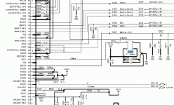
27Mhz oscillator is connected to pin #165 of 256pin SMD IC (MN35206UB)
My first intention is to try better spec clock, I don't know I encounter this problem.
27Mhz oscillator is connected to pin #165 of 256pin SMD IC (MN35206UB)
Attachments
lumanauw said:There are only 2 crystal/oscillator inside this unit. They are 5Mhz and 27Mhz. The 5Mhz crystal is connected to CPU, the 27Mhz is in the laser pickup.
My first intention is to try better spec clock, I don't know I encounter this problem.
27Mhz oscillator is connected to pin #165 of 256pin SMD IC (MN35206UB)
Yeah, just try KWAK-CLOCK with 27MHz FUNDAMENTAL MODE crystal.
Quarck in Manaus!dimitri said:
dimitri said:
thx, nice music.
Quark or Quasar?
Isn't a quark fundamental particle? Or a quasar?
[just kvetching here]

zinsula said:
Quarck in Manaus!

Isn't a quark fundamental particle? Or a quasar?
[just kvetching here]

- Status
- This old topic is closed. If you want to reopen this topic, contact a moderator using the "Report Post" button.
- Home
- Source & Line
- Digital Source
- DVD oscillator problem
