I tried reversed geometry 0306 capacitors, standing up on the short side, directly on the DAC chip legs of 1706 DAC
Ended up with Murata 4,7uF cap with actual PCB trace length of zero.
Only the internal bonding wire and leadframe left.
Since the inductance is getting reduced to approx 1/3 and capacitance 47 times bigger than 100nF original cap i assume the ripple was reduced.
My Denon CD player sounded much better.
I have a Pro-Ject pre-box s2 where i have not yet tried this.
It is not easy, you need really good soldering skills, a steady hand, microscope etc.
Will i risk anything modifying the Pro-Ject?
ESS is recommending an OP-amp buffering the 3.3V supply to the ESS9038... If this OP-amp powersupply driver would be loaded with 4,7uF would that OP regulation loop oscillate?
With the Project we design it to have active regulation across the audio BW (The DAC Array DAC AVCC Pins) - leaving the Polypropylene capacitors to decouple the rails.
With typical regulation there will be a crossover between Active regulation at LF and Passive "regulation" with the capacitors taking over SOMEWHERE within the audio BW, typically around 1KHz (which is really the worst from a SQ perspective).
The danger is lack of loop phase margin which will cause peaking around the crossover region - see the LM317 below, where the peaking can be seen on the noise floor (at around 900Hz), 0dB is referenced to 5v.
LM317 5V OP.jpg
The measured Loop Gain below shows around 45dB of Loop gain at 20KHz and a phase margin of around 75dB - which is around optimal for dynamic performance. (no peaking / well damped). Ignore the weirdness from 10K and below, this is due to poor current injection of the stimulus signal due to the low impedance at the FB node due to the high loop gain at LF (the FB loop is stimulated via transformer injection method).
ESS9311B 330pF 300R.png
You could try playing with the decoupling on 1.3V Core, 3V3D and 3V3 Osc (Clock) rails around the ES9038 DACs - the 1.3V Core is especially noisy due to the large fast current peaks from the digital core logic.
Pre Box S2 DAC Section.png
Sorry seems I cannot edit my post above,I meant to say "phase margin of around 75Deg - which is around optimal for dynamic performance, (no peaking / well damped)."
Last edited:
Thanks John for quick answer!
So IF i want to use a 0306 reverse geometry cap, directly on AVCC where the leadframe legs is entering the encapsulation of the DAC chip, should i go for a 4,7uF or 100nF?
I will try to take a picture from my Macro lens later tonight, so that everyone knows what i´m doing, English is not my native language so sometimes i feel limited in my way to express myself.
And if anyone want to experiment with this further i highly recommend to buy ten caps extra and practice on some scrapped circuit. The reason for saying that is that ended up Buying 3 DVD players of Denon 3930, to get one of them working. I destroyed the PCB, with extensive rebuilding, and trial and error.
Solder paste and hot air gun could be a faster and easier way to go but I have not tried that.
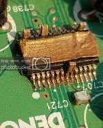
The board is one of my trial and error boards found in the garage.. oil and dust.
But you get my point. The inductance is extremely low... and tha cap is 47 times bigger (4,7uF) than the 100nF you find a mile away from the DAC.. The cap is a 0306 package "rewersed geometry" developed for extra low inductance, and high frequencies. [/IMG]
But you get my point. The inductance is extremely low... and tha cap is 47 times bigger (4,7uF) than the 100nF you find a mile away from the DAC.. The cap is a 0306 package "rewersed geometry" developed for extra low inductance, and high frequencies.
 [/IMG]
Last edited:
It is not easy, you need really good soldering skills, a steady hand, microscope etc.
I have done a few 64 pin TQFP PIC microcontrollers now. 0.5mm pitch.
I get the PIC lined up absolutely spot on, then glob some solder down one side.
I then glob plenty of solder on the other 3 sides.
Then with plenty of liquid or gel flux I use copper braid to remove excess solder.
I move the soldering iron along the braid and not the braid along the pins.
I did it wrong once and bent a couple of PIC pins !!!!
I have a row of vias on the pcb which connect to the PIC pins so I can DMM between PIC pins to check for shorts.
An externally hosted image should be here but it was not working when we last tested it.
Last edited:
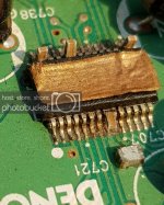
The inductance is extremely low... and tha cap is 47 times bigger (4,7uF) than the 100nF you find a mile away from the DAC.. The cap is a 0306 package "rewersed geometry" developed for extra low inductance, and high frequencies.
Inductance is not lowest the way you are using the caps. You have current flowing up one side, sort of branching out across, then back down the other side. That makes the effective current path higher inductance, folded around in a loop. For the low inductance specified, all current needs to be flowing principally in the direction of the shortest cap dimension. Not saying its a problem, however.
Last edited:
The board is one of my trial and error boards found in the garage.. oil and dust.
But you get my point. The inductance is extremely low... and tha cap is 47 times bigger (4,7uF) than the 100nF you find a mile away from the DAC.. The cap is a 0306 package "rewersed geometry" developed for extra low inductance, and high frequencies.http://s806.photobucket.com/user/kallekarr/media/Decoupling1.png.html
As Mark is getting at, the mounted inductance is swamped by the trace length / layout. I doubt it even makes a difference to use reverse geometry caps like this, but it does fit better I guess. Still, holy hell, clean that PCB with some alcohol and a toothbrush. It looks like a cat slept on your flux residue. 😀
Mark in other words you want to say that cap should be "lying instead nof standing" that others will understand easylly?
My current board (the third one) the cap is laying more on the leads. Cant hear that the sound is more relaxed but maybe...
If you find a better way to get 4,7uF CLOSER please share it below, i will certainly take all new ideas into consideration
I also made a battery supplied differential probe that i could use for power supply measurements down to uV ripple.
If you find a better way to get 4,7uF CLOSER please share it below, i will certainly take all new ideas into consideration
I also made a battery supplied differential probe that i could use for power supply measurements down to uV ripple.
You could try to solder 0402 capacitors onto the leads.
I would use an 1nF/NPO/0402/50V and if you have enough space you could use another 0402 capacitor, for example an 10uF/X5R/0402/6V3.
But it is also important to have a big electrolytic capacitor on the same supply rail with some ESR to minimize ripple on the supply and to prevent possible oscillations on the supply rail.
Oscillations on the supply rail can occur when you only use ceramic capacitors.
Well, 1nF is a small value and C0G is high Q. I'm not sure it's a great idea for the reasons you mentioned. The best decoupling cap is generally the highest capacitance for a given inductance (package).
AMEN to that Chris!!Well, 1nF is a small value and C0G is high Q. I'm not sure it's a great idea for the reasons you mentioned. The best decoupling cap is generally the highest capacitance for a given inductance (package).
Thats exactly what i had in mind. Now I want to try 10uF 4Volt 0306 caps on ES9038 DAC chip on my Pro-Ject Pre 2s.
I would use the 1nF/NP0/0402 capacitor for noise filtering.
A second 0402 capacitor with a higher capacitance would also fit on the IC pins.
It is hard to tell what available capacitance would be best because you also need to consider the DC bias characteristic of a class B capacitors.
Even with an 10uF/X5R/6.3V/0402 capacitor you probably only have 3.3uF capacitance left at 3.3V.
So probably a 100nF with a much better DC Bias characteristic would be better because so close at the pin you don't even need to compensate so much inductance.
As Chris719 writes, the upper frequency is only limited by the form factor, which is the geometry. The current length is the inductance! So if you can squeeze in 100uF in the same capsule size as 100nF they will have same inductance and the same upper frequency limit. That´s why I want the biggest possible cap with lowest inductance (smallest encapsulation, or most narrow with) as close to the DAC as possible.
LearnEMC - Estimating Connection Inductance
and
https://ewh.ieee.org/r3/enc/emcs/archive/2012-10-10b_DecouplingMyths.pdf
LearnEMC - Estimating Connection Inductance
and
https://ewh.ieee.org/r3/enc/emcs/archive/2012-10-10b_DecouplingMyths.pdf

Even with an 10uF/X5R/6.3V/0402 capacitor you probably only have 3.3uF capacitance left at 3.3V.
Fortunately TDK has a neat search facility that even lets you see the capacitance at your target DC bias. Using that I see that they don't have 10uF in 0402, they only go up to 4.7uF and that gives you just 1.35uF @3.3V. This capacitance doesn't change with the max working voltage of the cap - 4V, 6.3V and 10V all give the same.
Ahh, the realities of ceramic capacitors...
It’s nice to be able and experiment with combinations, the npo are great along with more lossy types, if the circuit allows using them without ringing. Have only done that on clocks though.
All my dacs have low loss electrolytics in a 6mm case size relatively close, with small ceramics near the pins.
- Status
- Not open for further replies.
- Home
- Source & Line
- Digital Line Level
- DAC chip decoupling