I guess this thread is here as the Blogs remain inactive. But I also suspect there may be a few of the more hardcore set who think that hacking our C code for an audio DSP makes sense...
Well I did, so that makes at least one of us (me)!
The current version of this crossover is solid and stable, but I haven't thrown in some of the more crazy bells and whistles that a "roll your own" in software allows.
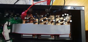
The thing looks like this:
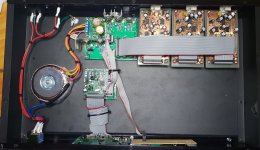
By my standards, tidy enough that I am happy - but not a thing of beuaty and wonder.
What is it? What is going on in that box?
The heart of the thing is the PIC32MZ2048:
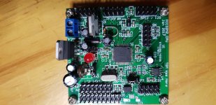
This is a generic PIC32MZ pcb that I use for all my projects. It comprises the PIC32, EEPROM, regs and headers for LCD and general I/O.
Running this 2 way crossover with 4th order slopes, and two parametric EQ's the memort is like 5%, RAM 7% and CPU load about 40% from what I see at 49,218ksps.
Huh? 49,218...
The reason for this is that this is an integer divisor of the 252MHz PIC clock, meaning the MCLK and LRCLK and BCLK are all nicely locked together without jitter.
In an embedded DSP, sticking to "normal" clock rates might look nice when you write the number down, but is actually meaningless. Unless you want to process digital data from external. Then I'd need to do a SRC... This clock rate works really nicely for the hardware...
The DSP has two "things" going on:
- The entire SPI read, DSP processing and SPI output occurs in an ISR that is triggered by the SPI buffer being half empty. Meaning this is rock steady on timing for keeping the SPI full for / from the ADC and DACS.
- The user interface is run when the ISR is not keeping things busy...
Other things in the box are the power supply and header breakout for the ADC and DACS...
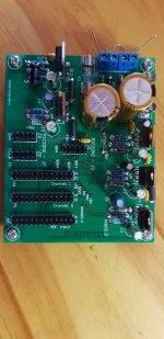
Not a lot to say here, supplies power and stops cables getting too out of control. Again I sent this PCB off to the fab, as I tend to do a bunch of audio stuff from the PIC, eg my signal generator uses this, as does my PC based distortion meter.
The ADC plugs onto the power supply PCB. Samples data rns across the ribbon cable (every second wire earth) to the power supply board, then back to the PIC.
The PIc sends SPI / I2S to the DACS, two of them in this case, again via the power supply PCB.
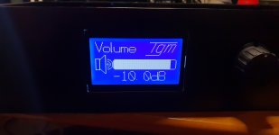
The user interface is on a 128 by 64 LCD, and is about as pretty as an engineer is likely to make it...
Volume control, with bar graph. In this case I am doing volume digitally. The tests I did against analogue volume chips showed that a CS4398 generates less distortion (if you can measure either of them). Its not that the analog chips are bad, but that the CS4398 is really good!
If you look on the right you might see the unloaded spot for the volume chips...
Save,Load config, Set up crossover, PArametrics.
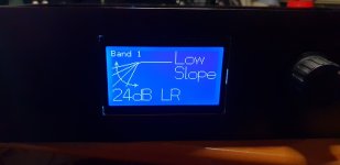
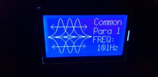
Select crossover slopes etc.
And delay.
The parametric is similar, choose your CF, Q and gain and off you go.
Things I ponder adding are compressors, limiters and suchlike. These would be a complete doddle to add, as it really is just peak tracking and comparisons - but the audiophile in me always stops me at the last minute.
With about 60% processing spare, I could add an extra channel or two, or a bunch more parametrics.
All audio processing in this is:
- 24 bit SPI / I2S in and out
- Converted to 32 bit data
- With 64 bit accumulator for all DSP functions which is shifted back to 32 bit for storage
By doing all this in integer things really click along, so there is great lattitude for other things. I am pondering effects eg for guitar.
This is all coded in C32, microchips free compiler, which at times frustrates the hell out of me. I am not really a programmer so relearn every time I do these things, and their documentation is - lets say - complicated.
So whats it cost me?
- The PICS cost less than a burger
- The breakout board has more in value in LM317s than the PIC I suspect...
- The ADC and DAC are the expensive bits...
- CS4398's are probably US$10
- CS5381 are a touch expensive, I have lots of these as I was using them for my distortion meter. Perhaps a CS5361 at US$10ish would be more sensible - their performance is not far off the CS5381.
As you can see those boards are home made - the input and output op amps are either NE5532 or LM4562, which in this implementation I cannot tell the difference between even using fancy test gear.
All up this is probably $200 of stuff from my shelves, and a ton of time.
If you would like to play with this, or the code, feel free to drop a line and I can copy it to you.
By the way, the code is close on identical to the code that controls my ADAU DSP crossover, but the DSP ISR (plus SPI/I2S interface) replaces the external ADAU chip...
Well I did, so that makes at least one of us (me)!
The current version of this crossover is solid and stable, but I haven't thrown in some of the more crazy bells and whistles that a "roll your own" in software allows.
The thing looks like this:

By my standards, tidy enough that I am happy - but not a thing of beuaty and wonder.
What is it? What is going on in that box?
The heart of the thing is the PIC32MZ2048:

This is a generic PIC32MZ pcb that I use for all my projects. It comprises the PIC32, EEPROM, regs and headers for LCD and general I/O.
Running this 2 way crossover with 4th order slopes, and two parametric EQ's the memort is like 5%, RAM 7% and CPU load about 40% from what I see at 49,218ksps.
Huh? 49,218...
The reason for this is that this is an integer divisor of the 252MHz PIC clock, meaning the MCLK and LRCLK and BCLK are all nicely locked together without jitter.
In an embedded DSP, sticking to "normal" clock rates might look nice when you write the number down, but is actually meaningless. Unless you want to process digital data from external. Then I'd need to do a SRC... This clock rate works really nicely for the hardware...
The DSP has two "things" going on:
- The entire SPI read, DSP processing and SPI output occurs in an ISR that is triggered by the SPI buffer being half empty. Meaning this is rock steady on timing for keeping the SPI full for / from the ADC and DACS.
- The user interface is run when the ISR is not keeping things busy...
Other things in the box are the power supply and header breakout for the ADC and DACS...

Not a lot to say here, supplies power and stops cables getting too out of control. Again I sent this PCB off to the fab, as I tend to do a bunch of audio stuff from the PIC, eg my signal generator uses this, as does my PC based distortion meter.
The ADC plugs onto the power supply PCB. Samples data rns across the ribbon cable (every second wire earth) to the power supply board, then back to the PIC.
The PIc sends SPI / I2S to the DACS, two of them in this case, again via the power supply PCB.
The user interface is on a 128 by 64 LCD, and is about as pretty as an engineer is likely to make it...
Volume control, with bar graph. In this case I am doing volume digitally. The tests I did against analogue volume chips showed that a CS4398 generates less distortion (if you can measure either of them). Its not that the analog chips are bad, but that the CS4398 is really good!
If you look on the right you might see the unloaded spot for the volume chips...

Save,Load config, Set up crossover, PArametrics.


Select crossover slopes etc.
And delay.
The parametric is similar, choose your CF, Q and gain and off you go.
Things I ponder adding are compressors, limiters and suchlike. These would be a complete doddle to add, as it really is just peak tracking and comparisons - but the audiophile in me always stops me at the last minute.
With about 60% processing spare, I could add an extra channel or two, or a bunch more parametrics.
All audio processing in this is:
- 24 bit SPI / I2S in and out
- Converted to 32 bit data
- With 64 bit accumulator for all DSP functions which is shifted back to 32 bit for storage
By doing all this in integer things really click along, so there is great lattitude for other things. I am pondering effects eg for guitar.
This is all coded in C32, microchips free compiler, which at times frustrates the hell out of me. I am not really a programmer so relearn every time I do these things, and their documentation is - lets say - complicated.
So whats it cost me?
- The PICS cost less than a burger
- The breakout board has more in value in LM317s than the PIC I suspect...
- The ADC and DAC are the expensive bits...
- CS4398's are probably US$10
- CS5381 are a touch expensive, I have lots of these as I was using them for my distortion meter. Perhaps a CS5361 at US$10ish would be more sensible - their performance is not far off the CS5381.
As you can see those boards are home made - the input and output op amps are either NE5532 or LM4562, which in this implementation I cannot tell the difference between even using fancy test gear.
All up this is probably $200 of stuff from my shelves, and a ton of time.
If you would like to play with this, or the code, feel free to drop a line and I can copy it to you.
By the way, the code is close on identical to the code that controls my ADAU DSP crossover, but the DSP ISR (plus SPI/I2S interface) replaces the external ADAU chip...
Last edited:
This uses the same ADC and DAC as I use in my distortion meter.
The devices are CS4398 and CS5381. Loopback levels of distortion on that are in the -115 to -120dB. (You seriously need balanced measurement system and to hold your tongue "just so" at these levels).
I expect similar here - but I do need to do the measurements.
The devices are CS4398 and CS5381. Loopback levels of distortion on that are in the -115 to -120dB. (You seriously need balanced measurement system and to hold your tongue "just so" at these levels).
I expect similar here - but I do need to do the measurements.
Some brief measurements.
I have not tried to optimise the levels etc here, other than using a level that gets good loopback on the distortion meter.
The optimal level for the DSP is likely different, but this will give a pretty good idea of what happens when you throw it into the test setup.
-1- Loopback
-2- With DSP XO in the loop
-3- How the connections were made.
Loopback perfromance of the distortion meter
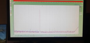
With DSP XO dropped in (blue channel is out, red in.)
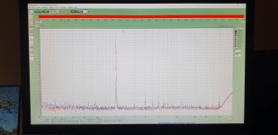
And the connections
Comment:
Moving the ground reference of the measurement channel from the input (ADC) to the output (DAC) card makes a 10dB shift in H2.
These measurements exclude noise.
There would likely be improvements with fiddling with levels, but I see it like: you dont get that choice in real life so how much difference does it make?
At 0.000X percent distortion I am pretty comfortable this will be OK.
I do imagine there will be artefacts if I use low frequency filters etc - in fact.... hmmm, the calculations for the IIR parameters are old and will be nowhere near 32 bit accurate - more like 20-24 if I recall...
I have not tried to optimise the levels etc here, other than using a level that gets good loopback on the distortion meter.
The optimal level for the DSP is likely different, but this will give a pretty good idea of what happens when you throw it into the test setup.
-1- Loopback
-2- With DSP XO in the loop
-3- How the connections were made.
Loopback perfromance of the distortion meter

With DSP XO dropped in (blue channel is out, red in.)

And the connections

Comment:
Moving the ground reference of the measurement channel from the input (ADC) to the output (DAC) card makes a 10dB shift in H2.
These measurements exclude noise.
There would likely be improvements with fiddling with levels, but I see it like: you dont get that choice in real life so how much difference does it make?
At 0.000X percent distortion I am pretty comfortable this will be OK.
I do imagine there will be artefacts if I use low frequency filters etc - in fact.... hmmm, the calculations for the IIR parameters are old and will be nowhere near 32 bit accurate - more like 20-24 if I recall...
The DSP implemented in the PIC32MZ begged me to add extra functions....
Spare processor cycles and bags of spare RAM (like 90% spare) is too tempting...
I updated the software in the PIC today, as having the processor sitting 60-70% of the time idle seemed silly.
Increasing the processing to add:
- Four common parametric equalisers that apply across all channels
- Two parametric equalisers that apply to the low channel
- Two parametric equalisers that apply to the low channel
In addition to the existing:
- 1st, second and fourth order low and high pass filters on the low channel (allowing subsonic cut)
- 1st, second and fourth order high pass filters on the high channel
Processing is still below 70%, so I might add some extra bells and whistles, but I honestly don't think there is a huge amount extra it needs.
I ran it for a few hours in a system, and it behaves well.
Important things like filter updates work, so changing filters, volume etc does not cause any unwanted clicks or pops. I have synchronised these updates using flags in the ISR and seem to have nailed it.
Distortion etc remains very low indeed, but noting again that to achieve numbers in the 0.000X percent region os NOT a matter of plugging in an RCA and getting these numbers, you eed balanced line connections to have a hope.
A very pleasant outcome.
Distortion etc remains very low indeed, but noting again that to achieve numbers in the 0.000X percent region os NOT a matter of plugging in an RCA and getting these numbers, you need balanced line connections to have a hope.
Here's some silly questions, and a heavy dose of assumptions:
I do not have anywhere near the same amount of skillset and knowledge you do, but recently I have arrived at this very conclusion.
RCA based equipment in general, and very low noise goals seems a bit difficult, and there is decent Pro equipment available using balanced interconnects, but the noise floor of power stages seem to be lagging behind a little bit?
Maybe power conditioning is not optimal/have not reached a high enough level?
There's a demand for high power capacity, relative/compared to pre stages, looking at power stages PSRR it seems the rejection ratio itself might be a limiting factor. Probably because power stages can not "lag", and when the demand for power is there, it should be delivered immediately.
A pre stage does not have the same power requirements, and regulating + some small caps here and there makes the power clean, which further helps signal integrity.
So it might be easier to make a cleaner PSU for the power stages, but how can that be done?
Battery banks work really well, but they are not practical.
How can one achieve switch mode PSU performance on par with a battery banks, for power amplifiers?
Most practical, real life implementations of power amps I've seen seem to go to maybe -108db THD+N at best.
I apologize for intruding with what might seem like off topic, but how are you planning on using equipment with, let's say -120db THD+N, without degrading the signal?
Kaffimann,
I am not planning or even really expecting to get anything useful with really low THD. It is more of an intellectual pursuit than anything.
on PSRR....
- power ampplifiers, at least those designed by sane people, use negative feedback to reduce the impact of this. It works, at least in the audible spectrum.
- Preamps - it is as you note pretty straight forward to maintain decent rail integrity here, and that combined with decent layout and NFB should do the trick.
The issue I see in measurements is earthing and the current paths you get if you connect inputs and outputs with multiple earths. The concept of the "earth" being a single reference plane is not true, and if you connect things such that currents flow through paths other than those you designed it for, spurs jump up everywhere.
So the simple act of connecting a distortion meter with an output (and earth associated with the DAC in the signal generator chain) and an input (AC with associated "ground reference") means you have lost control of where the two notionally "the same" but in fact different "earth" reference points connect.
By using balanced inputs on the ADC chain of the distortion meter this reduces the earth connection to a single point.
Even then though, where on the DSP you connect the earth reference balanced input maters.
Remember that -120dB relative to one volt is 1 microvolt.
If the device is driving say 10K at a volt, this is 0.1mA. You can generate 1 microvolt across 0.001 Ohms at 0.1mA... Now throw into the mix op aps and ADC / DACs with all manner of funny currents flowing... Reference points become critical.
Emilvv
Sure I can share the files. I will need to package them up, and remember this is not for the faint hearted!
- The PIC32MZ is a simple board. PCBCART made these and I imagine you could get more for a few bucks. It does use SMD.
- The PSU board is really simple. Again PCBCART has this.
- The ADC and DAC again use SMD. I dont think the latest version of these went to PCBCART, as the ones I pulled off my shelf were made at home. I have done the ADCs and DACs with PCBCART before, but these have lower THD.
- The LCD is standard off the shelf.
Fundamentally you could use the PIC32MZ and PSU and "bring your own" ADC or DACs. I designed the ADC and DAC boards to have a simple interface with:
- Power
- I2S (MCLK, LRCLK, BCLK, Data)
- SPI for the volume control (not used here)
- lots of ground.
I have built ADCs and DACs using both CS and AKM parts using this boarf form factor and interface allowing me to swap them in and out of gear, looking for "better" performance. (though this was in my distortion meter!).
So pretty much ANY ADC / DAC you can set up to work at about 48Ksp would work fine.
If I were doing this as a "project" to kit up, I would be sorely tempted to integrate the ADC and DACs onto one board, and put the PIC on the PSU board...
Last edited:
The PIC32MZ is a good little chip so long as you stay away from earlier versions which had bugs in them.
I went for the PIC32MZ1024EFG which worked fine for me as a USB oscilloscope.
I managed to get 2 mega samples/second.
I cheated and used MPLAB Harmony as the basic drivers for the USB and A2D.
I had to tweak the A2D to get full speed.
I went for the PIC32MZ1024EFG which worked fine for me as a USB oscilloscope.
I managed to get 2 mega samples/second.
I cheated and used MPLAB Harmony as the basic drivers for the USB and A2D.
I had to tweak the A2D to get full speed.
Nigel,
I need to get the USB running, I have never convinced myself to start down that path, but am convinced I should.
The part of the microchip domain that kind of annoys me is that Harmony should make things easy - but there are so many aspects that don't "just work". In my case I threw out their Audio drivers and wrote to the registers old fashioned style to set it up.
So I agree there have been hassles, in my case the bugs have been in the compiler and development environment.
I haven't had to tweak too hard yet, though I have:
- arranged the code so the compiler uses the MADD DSP instructions
- stopped optimisation on coefficient updates so that there are no "clicks and pops" caused by the compiler shuffling instructions like a deck of cards....
phil
Nigel,
I need to get the USB running, I have never convinced myself to start down that path, but am convinced I should.
The part of the microchip domain that kind of annoys me is that Harmony should make things easy - but there are so many aspects that don't "just work". In my case I threw out their Audio drivers and wrote to the registers old fashioned style to set it up.
So I agree there have been hassles, in my case the bugs have been in the compiler and development environment.
I haven't had to tweak too hard yet, though I have:
- arranged the code so the compiler uses the MADD DSP instructions
- stopped optimisation on coefficient updates so that there are no "clicks and pops" caused by the compiler shuffling instructions like a deck of cards....
phil
I started with a PIC18F4550 USB scope based on the code for the 4550 at Waiting for Friday – Weekend electronics engineering I managed to get 460,000 samples per second from the A2D.
I then moved on to the faster 50MHZ PIC32MX and found I could port a lot of the higher level USB across from app.h and app.c from the 4550 project.
However at that point I used Harmony for the basic lower level USB driver.
I managed to get about 1 mega samples/ second.
The PIC32MZ was a bit of a leap up as it was fine scale SMD and 200MHz.
I copied the top level code from the PIC32MX project and set up lower level USB using Harmony. It worked great except for a problem with the USB bus freezing 5 seconds after exiting the pc program.
Turned out Microchip had introduced a bug in Harmony 2.05 and 2.06.
Someone on Microchip forum told me about the bug so I reverted to Harmony 2.04 and things were ok then.
I had a problem early on with PIC32MZ in that for some strabge reason I had to fill up a buffer with data or the USB transmit buffer got corrupted.
It seems that the USB software reads the buffer from DMA so the cache is bypassed. So I used the "coherent" keyword with my transmit buffer and that problem went away.
The USB driver is a little touchy. Some settings have to be just right or it just doesn't work. On the 4550 I hadn't got the USB clock settings just right and I got no response from the PIC.
Harmony (when it works) is amazing but it does feel sometimes like Microchip bit off more than they could chew.
I am not planning or even really expecting to get anything useful with really low THD. It is more of an intellectual pursuit than anything.
Thank you for taking the time to reply.
Yes, That was my understanding, that you are doing this because you find it interesting, and because you have the opportunity and knowledge to do so.
The issue I see in measurements is earthing and the current paths you get if you connect inputs and outputs with multiple earths. The concept of the "earth" being a single reference plane is not true, and if you connect things such that currents flow through paths other than those you designed it for, spurs jump up everywhere.
And this was why I wanted to ask you those silly questions, because you seem to have an interest in signal integrity, and therefore probably have a decent grasp of what it takes to maintain a stable reference for that signal.
You also seem to be interested in cost/performance, and relative simplicity/KISS (Keep it Simple Stupid!).
And I was hoping, just a tiny little bit, that you might pick up an interest in coupling your DSP project together with a cost efficient low noise power stage of comparable quality, so the signal integrity/quality would remain intact all the way.
If this is the case, I am extremely interested in what that power stage might be.
Most of the power stages I have built are BJT based and either "Self" style blameless or somewhat modified - though I have built a ludicrous range of amplifier topologies just to see how they go.
As anyone on this list will know, unless you are trying pretty hard (for example by omitting feedback) getting power amp distortions below 0.0x% is not too hard.
Once you move down an order of magnitude and definitely when you shoot for 0.000x% things get very fiddly indeed.
I remember reading with some cynicism I must admit, about connectors adding distortion. Then while trying to measure the THD of an amplifier but getting crap results.
After hours of debugging I was puzzled to see vanishingly small distortion at the junction of the emitter resistors, but high distortion after the zobel...
It proved that the dummy load I was using had nichrome wire that was screwed to a terminal. The connection was very solid and I had no cause to think it would be problematic. This connection was non- linear, and the impedance of the zobel which IS Linear and IS non zero, was high enough that the voltage on the dummy load showed these attracts.
Using a big power resistor soldered to wire "fixed" things and the "apparent" distortion disappeared.
The lessons in this story to me are many, but include
- dont use crap test gear
- there is a point at which things like distortion become a numbers game, and diverge from practical reality
- even the most benign looking thing can screw things up at crazy low levels...
I have not, and honestly dont see myself, using balanced interconnects in my home gear.
- the sources are single ended
- the impact is really immaterial unless you mess up
I do use balanced line for
- specific measurement
- microphones or other low level stuff
- anything seeking to be professional or installed
Last edited:
I hear you, and thank you for the informed opinion.
But I think changing to balanced interconnects is a mandatory step in achieving higher signal quality. Not for sources, but for signal processing and routing between pre and power stages.
Balanced interconnects is a simple yet elegant solution to a problem, one signal in phase, the other out of phase, noise is everywhere and gets picked up, at the arrival point one of the signals are inverted, this makes the noise cancel itself out, and does nothing except add strength to the original signal.
This is how I understand it anyway, may not be 100% correct.
This standard comes from a time when signal integrity was a much bigger issue than it is today, in the digital age. But I think there is something to be learned from it.
Embrace the noise, in order to reduce it. Brilliant!
@googlyone did you use your own code for the DSP functions or code from Harmony?
I’m working on some music related projects and want to make my own DSP functions and I’m trying to understand how to call the DSP related assembly instructions in C.
I know XC32 is based upon or related to GCC.
I’m working on some music related projects and want to make my own DSP functions and I’m trying to understand how to call the DSP related assembly instructions in C.
I know XC32 is based upon or related to GCC.
@googlyone do you have experience in developing active crossover based on ADSP21489 using ADC and DAC separate boards instead of AD1939
I did my own code.@googlyone did you use your own code for the DSP functions or code from Harmony?
I’m working on some music related projects and want to make my own DSP functions and I’m trying to understand how to call the DSP related assembly instructions in C.
I know XC32 is based upon or related to GCC.
I have used Harmony for the general support functions, which when it is up and running is fine, but I find exceedingly frustrating to get working.
The actual DSP "functions" are very simple, and to be honest all the support around them such as working out coefficients, implementing filter parameter changes so that there are no clicks and pops etc etc etc is 95% of the work.
- Home
- Source & Line
- Digital Line Level
- DIY DSP crossover implemented in C on PIC32MZ