This is the must for the RF circuits only
[Markw4=rayma;]Agreed, one ground plane can be fine.[/Markw4]
There are may be occur additional interferences from DGND to AGND in this case
Basically, this is an RF circuit. The USB interface inside the PCM2912A uses an internal clock of 96 MHz and will generate lots of harmonics of 96 MHz. The built-in ADC and DACs are sigma-delta converters with 64 times oversampling. Sigma-delta converters are sensitive to interference at all frequencies except exact multiples of their clocks.
With a single-ground-plane design, one would typically complete each supply-decoupling cap-ground loop on the top layer and connect it to the ground plane at only one place. That way the current loops are kept local as much as possible. When there is a common supply for interfering and sensitive circuits, add ferrite beads in the supply connections to keep them separated.
In this case ( http://www.ti.com/lit/ds/symlink/pcm2912a.pdf pages 15 and 24), there is a USB supply that supplies lots of internal 3.3 V regulators for the various circuits, so these regulators handle the separation. These internal regulators have external decoupling.
Last edited:
I have mean what it is more relevant for RF , for 50 MHz this is much less important
Is it new design technique à la "star ground" by Thorp ?
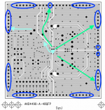
Actually it is a star ground à la AKM. Draw some colored lines on it, too.
Attachments
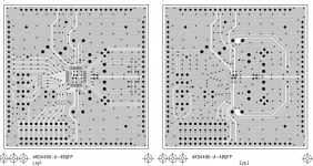
You may see the difference regarding your board .Actually it is a star ground à la AKM. Draw some colored lines on it, too.
At RF i have mean >200MHzBasically, this is an RF circuit.
How that 96MHz correlating with actual working frequency of the Sigma-Delta (which should be max 256*48=12.288MHz)?The USB interface inside the PCM2912A uses an internal clock of 96 MHz and will generate lots of harmonics of 96 MHz.
In this realization "supply-decoupling" should be very good to prevent undesirable returning current flow (to the input's capacitors)With a single-ground-plane design, one would typically complete each supply-decoupling cap-ground loop on the top layer and connect it to the ground plane at only one place.That way the current loops are kept local as much as possible.
Attachments
Last edited:
RF stands for radio frequency. There are many radio transmitters working well below 200 MHz. Besides the harmonics generated by the USB interface will extend well above 200 MHz.At RF i have mean >200MHz
Actually the sigma-delta is 64 times oversampled, so the clock frequency is at most 3.072 MHz.How that 96MHz correlating with actual working frequency of the Sigma-Delta (which should be max 256*48=12.288MHz)?
When it is 3.072 MHz, the spectrum of the digital sigma-delta modulate repeats every 3.072 MHz. The 31st image will then have a signal band centred around 95.232 MHz. Around 96 MHz, there will be strong out-of-band quantization noise, the 31st image of the out-of-band quantization noise around 96 MHz - 95.232 MHz = 768 kHz.
96 MHz interference on the reference or the clock of the DAC will frequency-convert this noise to low frequencies. A DAC by definition multiplies its digital input signal with its reference, and as I'm sure you know, multiplying mixers are good frequency converters.
The 62nd image may be worse than the 31st. Sigma-delta modulates often have a strong idle tone around odd multiples of half the clock rate and 62.5 times 3.072 MHz is 192 MHz, precisely the second harmonic of the USB clock. As long as the idle tone is converted exactly to 0 Hz no-one will hear it, but it will be frequency-modulated by the input signal.
In this realization "supply-decoupling" should be very good to prevent undesirable returning current flow (to the input's capacitors)
Indeed it should, but I'd be mainly worried about the signals that cross the border between digital and analogue and anything that can affect the reference voltage.
Last edited:
Radio frequency - Wikipedia
"Radio frequency (RF) refers to an oscillation rate of an alternating electric current or voltage or of a magnetic, electric or electromagnetic field or mechanical system in the frequency range from around twenty thousand times per second (20 kHz) to around three hundred billion times per second (300 GHz). This is roughly between the upper limit of audio frequencies and the lower limit of infrared frequencies."
"Radio frequency (RF) refers to an oscillation rate of an alternating electric current or voltage or of a magnetic, electric or electromagnetic field or mechanical system in the frequency range from around twenty thousand times per second (20 kHz) to around three hundred billion times per second (300 GHz). This is roughly between the upper limit of audio frequencies and the lower limit of infrared frequencies."
Last edited:
RF stands for radio frequency. There are many radio transmitters working well below 200 MHz.
Even the RF range from 3Hz to 30kHz is used for submarine communication.
Our AM broadcast band begins at 535kHz, though there is also much use below that.
Do you have a notion about sufficiency of "supply-decoupling cap-ground loop" caps values ? Is it enough 0.1uF ? Or maybe 2200uf?With a single-ground-plane design, one would typically complete each supply-decoupling cap-ground loop on the top layer and connect it to the ground plane at only one place. That way the current loops are kept local as much as possible.
The same , do you have notion about sufficiency of values of ferrite beads to separate clean AVDD from noisy DVDD? Is it enough 10uH Or it's needed 1000uH Or it's needed couple of them with different values?When there is a common supply for interfering and sensitive circuits, add ferrite beads in the supply connections to keep them separated.
Good question... It depends on what frequencies you are afraid of.
For a sigma-delta-modulator-based DAC that would typically be frequencies well above the audio band, especially near odd multiples of half the sigma-delta clock rate, because those can mix out-of-band quantization noise into the audio band. A BLM18RK102 (high-loss SMD ferrite bead with an inductance of about 6 uH) with a 10 uF X5R capacitor should then be more than sufficient. The resonance of this combination is at the upper edge of the audio band, but gets damped reasonably well by the DC resistance of the bead (Q ~= 1).
For a sigma-delta-modulator-based DAC that would typically be frequencies well above the audio band, especially near odd multiples of half the sigma-delta clock rate, because those can mix out-of-band quantization noise into the audio band. A BLM18RK102 (high-loss SMD ferrite bead with an inductance of about 6 uH) with a 10 uF X5R capacitor should then be more than sufficient. The resonance of this combination is at the upper edge of the audio band, but gets damped reasonably well by the DC resistance of the bead (Q ~= 1).
Last edited:
- Status
- This old topic is closed. If you want to reopen this topic, contact a moderator using the "Report Post" button.
- Home
- Source & Line
- Digital Line Level
- Ground Pours on a DAC PCB.