Hi All,
I've been playing around with upgrading an old Dacmagic 2, mostly as a learning exercise.
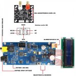
At the moment, I am struggling to get a new AK4118 based spdif->i2s reciever connected to the dacmagic i2s pins.
This is what I have so far:
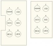
The AK4118 receiver has the following pinout:
3 - Data
4 - BCK
5 - MCLK
6 - LRCK
The Dacmagic 2 has the following data lines which I was planning to tap into
TP1 - CLK
TP2 - WS
TP3 - BCK
TP4 - A/A
TP5 - L/C
TP6 - EQ
My initial thought was to wire it as follows:
AK4118 -> Dacmagic
3-Data -> TP5-L/C
4-BCK -> TP3-BCK
5-MCLK -> not connected?
6-LRCK ->TP2-WS
But this produces no output.
The AK4118 reciever is showing a synced 44.1k signal, and the Dacmagic works fine with its own reciever.
Not sure how to diagnose this any further, so any help or pointers in the right direction would be much appreciated!
FYI, I have a cheapo USB logic analyzer, but I don't know much about debugging I2S so learning curve might be steep!
Thanks,
geoff.
I've been playing around with upgrading an old Dacmagic 2, mostly as a learning exercise.
At the moment, I am struggling to get a new AK4118 based spdif->i2s reciever connected to the dacmagic i2s pins.
This is what I have so far:
The AK4118 receiver has the following pinout:
3 - Data
4 - BCK
5 - MCLK
6 - LRCK
The Dacmagic 2 has the following data lines which I was planning to tap into
TP1 - CLK
TP2 - WS
TP3 - BCK
TP4 - A/A
TP5 - L/C
TP6 - EQ
My initial thought was to wire it as follows:
AK4118 -> Dacmagic
3-Data -> TP5-L/C
4-BCK -> TP3-BCK
5-MCLK -> not connected?
6-LRCK ->TP2-WS
But this produces no output.
The AK4118 reciever is showing a synced 44.1k signal, and the Dacmagic works fine with its own reciever.
Not sure how to diagnose this any further, so any help or pointers in the right direction would be much appreciated!
FYI, I have a cheapo USB logic analyzer, but I don't know much about debugging I2S so learning curve might be steep!
Thanks,
geoff.
Attachments
Last edited:
The TDA1305 DAC needs an MCLK (pin12), the schematic/pcb shows it should be supplied on TP1. Best connect pin5 of the AK4118 to this pin and see if this fixes it.
The TDA1305 DAC needs an MCLK (pin12), the schematic/pcb shows it should be supplied on TP1. Best connect pin5 of the AK4118 to this pin and see if this fixes it.
Thanks for the quick response! I've tried this now, but still not giving any output. Also tried unsoldering one side of the resistor on the dacmagic, as the clips were a bit loose.
Will see if I can spot anything else, just wanted to confirm that this should work in theory?
Thanks,
geoff.
Do you have a 0V connection between the AK4118 and the DACmagic board by any chance (a long shot I must admit) ?
Do you have a 0V connection between the AK4118 and the DACmagic board by any chance (a long shot I must admit) ?
Err, no. They're using separate transformers, so no 0v link.
Where should this go from / to?
Thanks,
geoff.
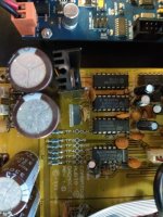
On the transmit side the 0V connection is pin2 (GND). At the DACmagic end there's no explicit connection for 0V so you'll need to create one. From the picture the nearest point to solder to looks to be pin7 of the 74HC04 (the bottom-most IC in the pic), this connected to the groundfill, which is 0V.
On the transmit side the 0V connection is pin2 (GND). At the DACmagic end there's no explicit connection for 0V so you'll need to create one. From the picture the nearest point to solder to looks to be pin7 of the 74HC04 (the bottom-most IC in the pic), this connected to the groundfill, which is 0V.
Tried that, but still no luck I'm afraid. Might have to abandon this and come up with an alternative plan (new dac board perhaps 😀 )
Thanks for all your help.
geoff.
Oh well, get yourself a TDA1387 board like this one as upgrade : tda1387 dac pcb "front end"
Funny you should mention that, I have a tda1387 dac kit on the way from China:
TDA1387 x8 DAC: let's check its design, mod it -or not-, play music -or not! 🙁-
Ah, that's one I've played with a lot in my journey of discovery with DACs 😀 You should be able to get a more satisfying sound with that than from the TDA1305 in the DACmagic.
Indeed, the dacmagic was a play thing that I picked up for just the postage, as the coax input was broken.
That other dac you posted a link to looks interesting (Philips Little Giant TDA1387), partly because the dacmagic already has 2 out of the 3 transformers required 🙂
Do you know how that compares to the tda1387 x8 dac?
That other dac you posted a link to looks interesting (Philips Little Giant TDA1387), partly because the dacmagic already has 2 out of the 3 transformers required 🙂
Do you know how that compares to the tda1387 x8 dac?
@matt_garman is the only one who's listened to that board that I'm aware of, he rates it as the best tda1387 implementation he's heard (that's just my interpretation, he might phrase it a little differently) and I think he had the *8 DAC a couple of years back.
I enjoyed the *8 but I did very substantial mods to it to get it to sing nicely. In the end I took the two transformers out of the box as it was limited by mains hum from their close proximity. If I recall there's now an improved version of that DAC available, let me see if I can find the link. It has more space inside the case for modding so might not need the trafos extracting to get the best from it.
This is it on Taobao, can't seem to access eBay right now : L1387DAC 8Xse???TDA1387hifi???????OTG??TDA1541-???
Last edited:
- Status
- Not open for further replies.
- Home
- Source & Line
- Digital Line Level
- Dacmagic 2 - i2s input lines