(Sorry if this is the wrong part of the forum by the way. Please move it if it is)
Hi, total noob here.
I've recently started working on a USB connected DAC after I've learned how to use the PCB design software EAGLE.
As a big fan of music and anything that comes with it, so I decided that making something I would enjoy using myself could be a nice project.
Currently I've properly connected and controled the XMOS XHRA-2HPA USB Audio controler and have it connected to a WM8741 DAC chip. Only what I don't understand is how to make the output of the DAC usable (and keeping up the high quality output with low distortion).
The DAC comes with 4 outputs VOUTLP (Positive out left), VOUTLN (Negative out left), VOUTRP (Positive out right), VOUTRN (negative out left).
Can I just route these connections to two RCA jack connectors and plug those into my pre-amp?
Do I need to use an opamp? I've been looking into the OPA1622 but I don't really understand how the circuitry around it is supposed to work and/or how to design the proper circuitry for my application (The resistors and capacitors)
The main goal is to use this DAC for my speakers and possibly in the future allow it to also drive my headphones (Regular 32ohm ones, nothing special. But just getting it to work on my main speakers would be cool already)
Can anyone help a total noob out? I'm willing to learn, but no idea where to start.
Last edited:
This isn't directly my field of expertise but I think your first move has to be to determine what type of output the DAC is. Typically it may be a 'current' output and that in turn needs an opamp configured as an I/V convertor in order to get a normal voltage output to feed to the external world.
https://www.by-rutgers.nl/IV-converter.html
Having a VPOS and VNEG output suggests a balanced type output, again no problem with opamps.
https://www.by-rutgers.nl/PDFiles/Balanced IV-converter.pdf
This is an alternative approach (not balanced) but gives some insight into how it all works.
http://www.diyaudio.com/forums/diyaudio-com-articles/172983-zen-i-v-converter.html
The DAC comes with 4 outputs VOUTLP (Positive out left), VOUTLN (Negative out left), VOUTRP (Positive out right), VOUTRN (negative out left).
Can I just route these connections to two RCA jack connectors and plug those into my pre-amp?
Re-reading your post and I might have misunderstood what you mean.
If the DAC is a commercial unit (ready to use) then you might be referring to balanced audio outputs with your VPOS and VNEG.
If so then you can either use one side of each, so VPOS and ground for one channel and again, VPOS and ground for the other channel.
You could also use opamps to make a balanced to unbalanced convertor which would then use both VPOS and VNEG outputs of each channel.
Figure 2 shows the kind of thing.
Balanced Line Driver & Receiver
(I'll move this to Digital Line Level)
Thanks for your reply, I'll check the documents and sites you've linked at
The pin descriptions are on page 7/8 of the datasheet, you can find it here: http://www.cirrus.com/en/pubs/proDatasheet/WM8741_v4.3.pdf
For both sides there is: Negative & Positive output, Negative & Positive reference and one midrail decoupling pin
From my understanding the reference pins just should be connected to the output pins, the mdirail I have no idea how to connect either but that is something I'll try to figure out after this.
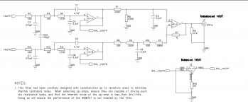
Right at the end of the data sheet is an application circuit.
So it actually is like I described in my second post above... the DAC is giving a balanced voltage feed. It is audio at this point but you need a 'reconstruction filter' to eliminate all the hash and noise from the DAC. The first two opamps do that and form a typical low pass filter. You will see BAL_VOUTP and BAL_VOUTN at the output of these first opamps. That is pure audio and is a balanced output. If you wish to have an unbalanced output (normal RCA type output) then you need the third opamp to convert the balanced feed to unbalanced.
So it actually is like I described in my second post above... the DAC is giving a balanced voltage feed. It is audio at this point but you need a 'reconstruction filter' to eliminate all the hash and noise from the DAC. The first two opamps do that and form a typical low pass filter. You will see BAL_VOUTP and BAL_VOUTN at the output of these first opamps. That is pure audio and is a balanced output. If you wish to have an unbalanced output (normal RCA type output) then you need the third opamp to convert the balanced feed to unbalanced.
Attachments
I totally missed that!
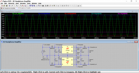
I've recreated the circuitry in that schematic in my PCB design software's schematic.
It looks like this, which should be alright and working if I'm not mistaken?

I've recreated the circuitry in that schematic in my PCB design software's schematic.
It looks like this, which should be alright and working if I'm not mistaken?
The opamps will need a dual supply and so pin 4 should go to -15 volts or whatever you are using.
Can you elaborate on that?
Can I buy a 15V +/- supply or would I need to make it myself? If so, what is the recommended design?
Can I buy a 15V +/- supply or would I need to make it myself? If so, what is the recommended design?
The voltage isn't an absolute or even critical, anywhere from -/+5 volts to -/+15 should be OK.
A dual or split supply is having a positive rail above ground and a negative rail below ground.
There are several ways to obtain a negative rail depending on what you have available.
1/ A separate mains transformer, bridge rectifier and caps plus a couple of voltage regulators.
2/ A small DC/DC convertor (these are cheap) that would take the DAC supply and generate a plus and a minus rail. These are good but not the best option for ultra low noise.
3/ If you have the circuit for the DAC PSU then it should be possible to add a negative rail. This diagram shows a split supply derived from a single AC input voltage. The regulators could be three terminal LM317/337 types or 78/7912 etc.
Attachments
Right now I got this:

which should make a negative and positive amount of voltage. 18V is used in this example but if thats not recommended it can obviously be replaced with two supplies of that voltage.
The only thing I worry about is the amount of noise and ripple this will introduce into the audio signal.
I don't have access to the power supply's circuit, I don't have the experience to make my own AC/DC converter without being in danger.
Which solution do you recommend? With size and price taken into consideration, I'm not looking for the cheapest solution but I do prefer to use something that both good and not super expensive to build (Either due the price of the parts or needing a huge PCB)
EDIT: Would otherwise be 2x24V-DC in, turning it into 24V/-24V (Like the example above) and then having a voltage regulator bring it down to 18V/-18V be good enough to get rid of most of the ripple?
Last edited:
If you can't access the DAC PSU then you have to add an additional one. The cleanest solution is a small transformer and the usual rectifier/cap/regulator.
Using two 24 supplies is possible (but it sounds messy) and both would need to be totally isolated from each other and from any mains ground (otherwise they would short each other out when coupled up).
Power Supply for Preamps
Later version:
Power Supply for Preamps
-/+12 or -/+15 volts dc is ideal for most opamps.
Sorry for the short amount of silence but I finally found some time again to work on this project.
I currently got in contact with a manufacture of power supplies and they offer a 5V/15V/-15V triple output supply.
5V: 50mV ripple
15V/-15V: 100mV ripple
I currently got a 1200uF capacitor for the 5V, (Together with two 22uF and one 0.1uF) which should keep the ripple down enough. the 5V will have a max. load of 900mA
As for the -/+ 15V I got a 3300uF capacitor for both inputs and I'm thinking about getting a linier voltage regulator for both to get it down to a clean stable 12V, bundled with another 440uF capacitor on the regulator's output.
Is the voltage regulator a proper solution? Or do you think the power line is already clean enough with the 3300uF for use with the op-amps @ 15V? Maybe if I'd go for the regulator-less solution I should add a few more different type (Poly-Tant, Ceramic etc.) capacitors to filter the last little bit of ripple out some more?
Thanks in advance!
That power supply sounds like it could be a switch mode type. 100mv ripple is extremely high.
I thought of this (link in post #1)
http://www.diyaudio.com/forums/vend...ntswitcher-mains-free-15v-6-5-3-3v-power.html
I thought of this (link in post #1)
http://www.diyaudio.com/forums/vend...ntswitcher-mains-free-15v-6-5-3-3v-power.html
It's definitely a switching supply with a high ripple, it's definitely needed to get the ripple down so it doesn't noticeably distort the audio.
I'm trying to make trade-offs between Quality and Price, the SilentSwitcher looks really nice but the price of just the supply equals the price of the PCB + components, basically doubling the costs.
A slight amount of ripple is acceptable, just not 100mV, that's why I want to bring it down by atleast a factor 10
I've tried to look for one but I can't find one thats good and affordable, can you direct me to one?
Please remember that I need both 5V, 15V and -15V. It can be split in two (1x 5V & 1x15+-15V) supplies.
Is there really no way to make the switching supply work properly for a DAC? This charger is rather affordable and I know the spec. sheet matches its performance.
Please remember that I need both 5V, 15V and -15V. It can be split in two (1x 5V & 1x15+-15V) supplies.
Is there really no way to make the switching supply work properly for a DAC? This charger is rather affordable and I know the spec. sheet matches its performance.
Well you have two (potential) problems with an SMPS. One is noise and hash that might be radiated electromagnetically and so picked up by and induced into nearby wiring and circuitry. Space and a metal enclosure are your friends here. The other problem is attenuating the high frequency ripple. There are a number of solutions but all involve more than just adding extra capacitance. For example an R/C/R/C type network might be a big improvement or even substitution of the resistors by inductors could be a better option.
A low drop out 12 volts (and minus 12 volt) regulator would help as well but the performance of regulators always deteriorates at higher frequencies.
I can't just name any ready built linear regs simply because they are more the kind of thing you could build yourself very easily.
Quick search turns up:
VELLEMAN KIT - K8042 - Symmetric 1A Power Supply Kit | CPC UK
And for 5 volts:
VELLEMAN KIT - K1823 - 1A POWER SUPPLY | CPC UK
At one point I was looking at some doorbell transformers for a dac board I have here, they were somewhere between 15 and 17 volts if I recall.
Maybe those, and some lm317 regulators would get you going, at least for the output stage.
I miss the days of being able to find more second hand transformers, everything is switch mode...
Maybe those, and some lm317 regulators would get you going, at least for the output stage.
I miss the days of being able to find more second hand transformers, everything is switch mode...
- Status
- Not open for further replies.
- Home
- Source & Line
- Digital Line Level
- New to all this, how to make my DAC's (WM8741) output useable?