Hi,
I have no DAC currently in my audio system. I use my PASS B1 & PASS ALEPH J or Thorens AZ-25 on Elision 1400 speaker. They are drive by the audio analog output of the Macbook when I listened Flac track or from the analog output of an apple Express when I listened to streaming on deezer.
I plan to make a DAC with "no DAC chip " using the idea explained is the thread : http://www.diyaudio.com/forums/digital-line-level/273474-best-dac-no-dac.html
I will post the construction of the DAC here with picture.")
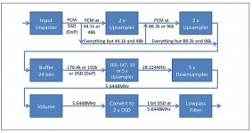
The idea is to apply a low pass filter directly on the DSD numerical signal, so there is no need for a digital to analog chip.
A software like HQ Player is use to convert on the fly PCM file to DSD.
Have you tested this method, what is your opinion. Is the sound good ? How does it compare to an ESS chip ?
I have a lot of questions about this kind of solution.
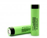
I plan to use the AK4137 chip powered with Panasonic Li-ion batery.
The battery can be found here and are very good : https://www.fasttech.com/products/1141100
It convert PCM to DSD so I do not need to use a software like HQ player. With this solution I'll be able to listened to my flac track or to stream music with airplay. The PCM will be converted in DSD. I'll also be able to listed to native DSD.
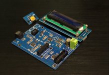
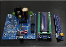
There is two kit on the internet :
AK4137 DAC SRC Flagship High End Audio 786K 32bit DSD256 DSD IIS Conversion | eBay
Ak4137 DAC SRC phare haut de gamme audio 786 K 32Bit DSD 256 DSD IIS conversion dans Amplificateurs de Consumer Electronics sur AliExpress.com | Alibaba Group
What is the best kit and is it a good solution to start ?
What type of USB to I2B board should I buy ?
What is the cut off frequency of the low pass filter ? Do you use LC or RC low pass filter ? I think I will go on LC low pass filter.
Here a good documentation about DSD format by sony : http://www.sony.net/Products/SC-HP/cx_news_archives/img/pdf/vol_17/tw_saud.pdf
" DSD is close to analog
Although this 1-bit data stream is a digi- tal signal, it is extremely close to the analog signal that is the original audio material. Simply by passing the signal
through waveform shaping and low- pass filter circuits DSD is able to re- produce the original audio signal faith- fully."
Thanks in advances for your help !
I have no DAC currently in my audio system. I use my PASS B1 & PASS ALEPH J or Thorens AZ-25 on Elision 1400 speaker. They are drive by the audio analog output of the Macbook when I listened Flac track or from the analog output of an apple Express when I listened to streaming on deezer.
I plan to make a DAC with "no DAC chip " using the idea explained is the thread : http://www.diyaudio.com/forums/digital-line-level/273474-best-dac-no-dac.html
I will post the construction of the DAC here with picture.
The idea is to apply a low pass filter directly on the DSD numerical signal, so there is no need for a digital to analog chip.
A software like HQ Player is use to convert on the fly PCM file to DSD.
Have you tested this method, what is your opinion. Is the sound good ? How does it compare to an ESS chip ?
I have a lot of questions about this kind of solution.
I plan to use the AK4137 chip powered with Panasonic Li-ion batery.
The battery can be found here and are very good : https://www.fasttech.com/products/1141100
It convert PCM to DSD so I do not need to use a software like HQ player. With this solution I'll be able to listened to my flac track or to stream music with airplay. The PCM will be converted in DSD. I'll also be able to listed to native DSD.
There is two kit on the internet :
AK4137 DAC SRC Flagship High End Audio 786K 32bit DSD256 DSD IIS Conversion | eBay
Ak4137 DAC SRC phare haut de gamme audio 786 K 32Bit DSD 256 DSD IIS conversion dans Amplificateurs de Consumer Electronics sur AliExpress.com | Alibaba Group
What is the best kit and is it a good solution to start ?
What type of USB to I2B board should I buy ?
What is the cut off frequency of the low pass filter ? Do you use LC or RC low pass filter ? I think I will go on LC low pass filter.
Here a good documentation about DSD format by sony : http://www.sony.net/Products/SC-HP/cx_news_archives/img/pdf/vol_17/tw_saud.pdf
" DSD is close to analog
Although this 1-bit data stream is a digi- tal signal, it is extremely close to the analog signal that is the original audio material. Simply by passing the signal
through waveform shaping and low- pass filter circuits DSD is able to re- produce the original audio signal faith- fully."
Thanks in advances for your help !
Attachments
Last edited:
@vladimirb0b yes LTspice have an FTT fonction but I don't know how to do your simulation. From where come your 1KHz noise ? Power supply or DSD decoding ?
Here is a good article about DSD : http://www.muszeroldal.hu/assistance/dsd.pdf
It say " In addition, SACD players must low-pass-filter their analog output above 50kHz" , so I will start with a 50 KHz low pass filter. I will make a LC filter first and plot the picture response here.
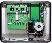
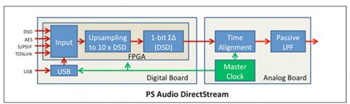
There is a commercial DAC witch do the same thing: the PS Audio Direct stream DAC.
6moons audio reviews: PS Audio DirectStream PerfectWave DAC
It uses a FPGA in place of the AK4137 chip to process the PCM to DSD conversion. And the use low pass filter to have the analog output. We can see the choke on the picture.
Here is a good article about DSD : http://www.muszeroldal.hu/assistance/dsd.pdf
It say " In addition, SACD players must low-pass-filter their analog output above 50kHz" , so I will start with a 50 KHz low pass filter. I will make a LC filter first and plot the picture response here.
There is a commercial DAC witch do the same thing: the PS Audio Direct stream DAC.
6moons audio reviews: PS Audio DirectStream PerfectWave DAC
It uses a FPGA in place of the AK4137 chip to process the PCM to DSD conversion. And the use low pass filter to have the analog output. We can see the choke on the picture.
Attachments
Last edited:
@vladimirb0b yes LTspice have an FTT fonction but I don't know how to do your simulation. From where come your 1KHz noise ? Power supply or DSD decoding ?
...
I will make a LC filter first and plot the picture response here.
I got my test tone by converting 384 kHz 24 bit sine wave tone to DSD and then to wav with mansr's SoX. He says it works and it appears to. PM me an email address that accepts large enough attachments (gmail) and I will send it to you.
You will probably find you need some R but if you can make it without, so much the better.
I'm quite skeptical about one-pass LPF that could cut 11MHz well. One of working solutions is DSC-1 DAC (that I am listening to now) being discussed in a neighboring thread. It downshifts the frequency to somewhat edible 384k using an analog window filter, and only after it there are 3 regular S-K filters. However it does have an own penalty of quite high levels of correlated noise.
Let's think how many steps we need to actually cut 11MHz below -150..160dB (so it NEVER comes out) and maybe its intermod products as well.
Let's think how many steps we need to actually cut 11MHz below -150..160dB (so it NEVER comes out) and maybe its intermod products as well.
I've put up a 4th order LC filter suited to DSD filtering in this thread - http://www.diyaudio.com/forums/digital-line-level/235144-low-pass-filter-dsd.html
Thank you. As I understand, you've put this after a DAC chip, not just bare DSD meander.I've put up a 4th order LC filter suited to DSD filtering in this thread - http://www.diyaudio.com/forums/digital-line-level/235144-low-pass-filter-dsd.html
Actually I'm concerned much on filtering the RF part out. 11MHz!!! It must be getting everywhere.
Its fairly agnostic as to what feeds into it.
Due to DSD's extreme sensitivity to jitter I'd recommend feeding it with a transversal filter rather like Jussi's design (DSC1). Certainly a transversal filter helps a lot with the extreme HF filtering.
<edit> I see you're listening to one of those already, I am curious as to what causes the correlated noise. It could be down to inter-symbol interference as the design's using 100% modulation. Bruno Putzeys points out the RTZ approach avoids ISI, you'd need to run up 4X the clock rate though to implement that. I recall the CS4303 data sheet from Crystal Semiconductor explained this approach (page 8).
Last edited:
Well, 4x over 11MHz we already have? OK, can do, but need to convert the PWM-like stream to RTZ. Lemme think...Bruno Putzeys points out the RTZ approach avoids ISI, you'd need to run up 4X the clock rate though to implement that.
Thank you.
Yup. I just merged 2 chinese proto boards as of now: AK4137 oversampler and Jussi-like DAC. Everything I've changed is JLSounds isolated XMOS module instead of Chinese one, and some I/V stage mod, getting rid of CFA. The rest was untouched right to the moment when my customer (well, a probable customer ) grabbed the proto just from my desk, after a hour of listening, and leaped away laughing happily. So I've ordered a new board and a pouch of resistors.
The prob is very quiet random chirping tone that "complements" qiuet passages on the track. The louder is the music, the quieter is the noise, and vice versa. I haven't had enough time to investigate it, but realized that square-window transversal filter attenuates the "main tone" next to nothing. Am thinking of implementing Blackman's window (all coefficients positive instead of say Kaiser) but there will be a LOT of pain with resistor values. All the simplicity goes to hell.
) grabbed the proto just from my desk, after a hour of listening, and leaped away laughing happily. So I've ordered a new board and a pouch of resistors.The prob is very quiet random chirping tone that "complements" qiuet passages on the track. The louder is the music, the quieter is the noise, and vice versa. I haven't had enough time to investigate it, but realized that square-window transversal filter attenuates the "main tone" next to nothing. Am thinking of implementing Blackman's window (all coefficients positive instead of say Kaiser) but there will be a LOT of pain with resistor values. All the simplicity goes to hell.
My suspicion (beyond the ISI issue) would fall first on your power supply. If you're using logic gates (I believe Jussi was using 74595s of some logic family) then their PSRR (or rather lack of it) would be the no.1 issue. But its hard for me to see how insufficient PSRR relates to the noise level being the inverse of the music level. Perhaps that really is down to ISI because the maximum number of transitions occur at the zero crossing.
Thanks for supporting my bare thoughts, abraxalito. I will post my results here, after I win.
Power supplies are rock solid Jung-style regulators with sense just on the registers' legs, so I'm pretty sure there's nothing to be improved.
The things that can be, however, the whole board layout and grounding. Also I'm unsure whether I should try bipolar I/V conversion instead of unipolar: I will try to bias the I/V stage with 2.5V instead of 0, considering that 74's outputs are fully pushpull.
About NRZ to RZ... if I convert the DSD stream (which requires a few elements actually), what will I get on the filter output? Trying to imagine but feel too dumb.
I'd not rule out power supplies as contributors to your issues so easily, based on my own experience with DACs. When the power supply's actively regulated the regulator gobbles up noise and regurgitates it - see the tests done (I believe suggested by peufeu) where regs are fed a sine wave and their generated harmonics monitored. In the case where the DACs going to be putting HF on the rails the original Jung-Didden regulator with the AD797 got modified into a variant with a JFET input amp (AD825 was it? my recollection isn't secure) because the bipolar part was RF susceptible.
You could try LC filtering between the Jung reg and the logic chips to see if anything changes.
What are you using for I/V stage? With a CMOS logic chip the output's not going to be a current source, rather it'll look like a bare resistor to one or other of the rails.
If you've not yet downloaded it, search for the CS4303 data sheet to get a feel for how the RTZ modulation works.
1. LC filters present by design. I doubted whether to short or to leave them, and left intact. However in my next incarnation I'll put a bead near every chip, despite that my scope shows nothing criminal.
The opamps in the regs are op27, bipolar. Hm.
2. I/V stage is classical "virtual ground" solution using AD744/LME49713 composite. What is a resistor to a rail but a current source?
3. Reading it 3rd time, thank you. Finally I will get it.
The opamps in the regs are op27, bipolar. Hm.
2. I/V stage is classical "virtual ground" solution using AD744/LME49713 composite. What is a resistor to a rail but a current source?
3. Reading it 3rd time, thank you. Finally I will get it.
I doubt that a bead (normally inductive in the vicinity of 1uH) would offer you much attenuation where you're really needing it (from just above the audio band). I was thinking of more aggressive filtering that might come about from much higher inductance (100uH minimum). TDK make some 7mm diameter inductors which I've used to fairly good effect.
For sure I'd suspect OP27 opamps in the regulator as being RF sensitive.
I'd be tempted to try to use your DAC in 'voltage mode' rather than 'current mode' and see if it rejects noise better. Partly the reason for that is when the op amp is generating the 'virtual ground' by negative feedback its going to have rising input impedance at HF meaning HF PSRR is going to suck fairly badly. A discrete buffer (say using something like a BF862) could potentially present a very light load many orders of magnitude higher than the logic's output impedance, including at HF.
Just a few fairly random thoughts...
Thanks again.
Voltage mode... hm. Looks pretty reasonable, taking that TTL outputs are bipolar. Will try both bipolar I/V and V mode, when the board arrives finally. Predict no cardinal difference.
Op27... right. Will try something jfet and faster. Maybe even for each register separately (crazy but if it works....)
The louder is the music, the quieter is the noise, and vice versa.
Have you verified this or could it be that the noise level is consistent and is simply just more, or less, audible depending on the music level?
I seem to recall that somebody experimenting with a DSD solution experienced noise that was eliminated by disabling/disconnecting the sensing on their regulated PS; I think they were using a Salas Reflektor D.
I'm not able to dig the problem at the moment, as the prototype is not with me. Am waiting for another pcb.
I was told by a clever person that 5th order SDM in Ak4137 is not optimal for idle-tone suppression (and there's no hardware in Jussi's design that cancels it) and that's the case. No, the noise is not continuous, it's audibly signal related.
Terminal case would be an own SDM design. Quite a task...
- Status
- This old topic is closed. If you want to reopen this topic, contact a moderator using the "Report Post" button.
- Home
- Source & Line
- Digital Line Level
- DSD no DAC project