PCM5102 USB DAC (simplified)
edit: the project changed quite a bit. See a few posts down.
I wasn't sure in which forum to post this one... the aim of the project is to build a compact USB DAC that would be able to decently power higher impedance headphones such as the sennheiser hd650.
The design constraints (my whims if you prefer) are:
- the pcb must be able to fit in the Hammond 1455b1002. The case is sized as 72*100*19mm (external). There's only 10mm in between the pcb and the top of the case in that one btw.
- the device should be powered only from the USB bus.
- ideally, it should be isolated from the computer to interrupt groundloops if connected to an external amplifier.
- as I'm no manufacturer and don't intend to become one, only parts I can buy at mouser are considered. So no ES9023 nor SA9023 nor TE7022 for me.
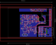
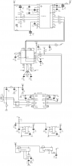
All this led me to consider a solution with ADUM4160-PCM2707-PCM5102 on the digital side, powered from a Murata 5V-5V DC-DC converter. The schematic has the details. On the analog output side, I'm considering a multiloop amp made from an opa2134 and a lm6172, powered from a 5v to +/-9V DC-DC converter (schematic and layout still to come for the amp). A RK097 will serve as volume control and will be panel-mounted, as well as the output jack.
I attached both schem and layout for the digital part. The pcm2707 has many pins removed (all the ones that can stay open), a bad habit of mine to simplify layout.
To give credits where it's due, there's some inspiration from layouts posted by marce for the usb input and I received helpful comments on parts selection from Avro-Arrow on head-fi. The multiloop amp idea is coming from reading jcx's posts (who else ?). Sorry for the mess I'm doing with their ideas. The rest is datasheets' standard designs.
Which brings me to my unresolved questions or hesitations...
- Host pin on the pcm2707: the datasheet says "Host detection during self-powered operation (connect to VBUS). Max power select during bus-powered operation. (LOW: 100 mA, HIGH: 500 mA)." Is there truly a point in setting it to high ? It's clear that the device will draw more than 100mA as a whole. If I set it to high, I can just tie it to the VCCP pin next to it, can't I ?
- Supply pins decoupling and bypass on the PCM5102: after the regs, I'm planning a ferrite followed by a 10uF polymer in // with a 2.2uF X7R on the three power pins. The values are closed enough that resonances should be tamed. Any reasons I shouldn't go that road ?
- Gnd connection in between the dac and the future amp section: the two dc-dc converters are isolated so I'm pretty free wrt where I connect the two sections grounds. I had planned to connect them only at the potentiometer (keeping in mind it will be connected by wires to pads on the pcb). Bad idea?
- Grounding of the enclosure: to which ground ? Computer ground ? It seems the best way to actually ground the case when used only with headphones.
- Digital power and dc-dc noise: is the filtering too light on the 5V line or does it seem allright ? For the headamp section, I'll add a cap multiplier to remove switching noise (the murata switch at about 60-70khz iirc). But I don't have 1V to burn for the pcm2707.
I probably forgot tons of things and overlooked many a problem. Please shoot away.
I've got nothing to offer but my thanks for any help and the promise to post the eagle files once I'm certain it works.
edit: the project changed quite a bit. See a few posts down.
I wasn't sure in which forum to post this one... the aim of the project is to build a compact USB DAC that would be able to decently power higher impedance headphones such as the sennheiser hd650.
The design constraints (my whims if you prefer) are:
- the pcb must be able to fit in the Hammond 1455b1002. The case is sized as 72*100*19mm (external). There's only 10mm in between the pcb and the top of the case in that one btw.
- the device should be powered only from the USB bus.
- ideally, it should be isolated from the computer to interrupt groundloops if connected to an external amplifier.
- as I'm no manufacturer and don't intend to become one, only parts I can buy at mouser are considered. So no ES9023 nor SA9023 nor TE7022 for me.
All this led me to consider a solution with ADUM4160-PCM2707-PCM5102 on the digital side, powered from a Murata 5V-5V DC-DC converter. The schematic has the details. On the analog output side, I'm considering a multiloop amp made from an opa2134 and a lm6172, powered from a 5v to +/-9V DC-DC converter (schematic and layout still to come for the amp). A RK097 will serve as volume control and will be panel-mounted, as well as the output jack.
I attached both schem and layout for the digital part. The pcm2707 has many pins removed (all the ones that can stay open), a bad habit of mine to simplify layout.
To give credits where it's due, there's some inspiration from layouts posted by marce for the usb input and I received helpful comments on parts selection from Avro-Arrow on head-fi. The multiloop amp idea is coming from reading jcx's posts (who else ?). Sorry for the mess I'm doing with their ideas. The rest is datasheets' standard designs.
Which brings me to my unresolved questions or hesitations...
- Host pin on the pcm2707: the datasheet says "Host detection during self-powered operation (connect to VBUS). Max power select during bus-powered operation. (LOW: 100 mA, HIGH: 500 mA)." Is there truly a point in setting it to high ? It's clear that the device will draw more than 100mA as a whole. If I set it to high, I can just tie it to the VCCP pin next to it, can't I ?
- Supply pins decoupling and bypass on the PCM5102: after the regs, I'm planning a ferrite followed by a 10uF polymer in // with a 2.2uF X7R on the three power pins. The values are closed enough that resonances should be tamed. Any reasons I shouldn't go that road ?
- Gnd connection in between the dac and the future amp section: the two dc-dc converters are isolated so I'm pretty free wrt where I connect the two sections grounds. I had planned to connect them only at the potentiometer (keeping in mind it will be connected by wires to pads on the pcb). Bad idea?
- Grounding of the enclosure: to which ground ? Computer ground ? It seems the best way to actually ground the case when used only with headphones.
- Digital power and dc-dc noise: is the filtering too light on the 5V line or does it seem allright ? For the headamp section, I'll add a cap multiplier to remove switching noise (the murata switch at about 60-70khz iirc). But I don't have 1V to burn for the pcm2707.
I probably forgot tons of things and overlooked many a problem. Please shoot away.
I've got nothing to offer but my thanks for any help and the promise to post the eagle files once I'm certain it works.
Attachments
Last edited:
Why don't you use a DC-DC with more than 5 volts so you will have some
voltage to burn in a filter..?
There is no point in setting the host to high power...it's only powering the ADuM.
You can use ADuM3160...it costs less and you don't need the extra isolation.
The enclosure should be grounded back to the computer with a high value resistor
and cap.
voltage to burn in a filter..?
There is no point in setting the host to high power...it's only powering the ADuM.
You can use ADuM3160...it costs less and you don't need the extra isolation.
The enclosure should be grounded back to the computer with a high value resistor
and cap.
The enclosure should be grounded back to the computer with a high value resistor and cap.
Thx. For future reference, I found this post which goes into more details.
And yes, the adum3160 is a significantly cheaper.
DC-DC converter to 6V aren't that common. I found a Murata one though in the MTE1 SMD serie.
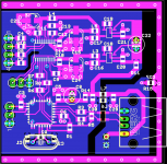
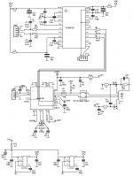
I decided to simplify things. No more isolation for the dac section and the headphones amp will be on its own board. If I want isolation, I'll buy a doodblebug.
Size is thus back to 50*50mm. I'll use slightly taller and narrower hammond case (1455C1201 for example). Either 80mm deep for a stand alone dac or 120mm for a dac+headamp.
What was added: gnd shield to link the case to usb shield, jumpers to set host on the pcm2707 and the digital filter on the pcm5102, pads to tap the usb power for the headamp.
Attachments
I spent some time checking the circuit pin-by-pin and it seems allright. Printing it also doesn't reveal anything wrong (except that it's going to be a pain to solder).
So here's the Oshpark share, if someone is feeling adventurous. It is untested: I'll build one myself but I won't get the pcb before a month at best. It is also possible to download the .brd file from oshpark to create gerbers if you prefer another pcb factory. I'll upload a BOM in the coming days.
https://oshpark.com/shared_projects/eeKhgtvj
The soldering isn't as bad as you might think. I've worked with the PCM2707 (PupDAC) and the PCM5102A (my own design) and the only main problem you have is getting the alignment right. Solder the first pin on the board, and while heating it use your tweezers to align the entire chip with the pads on the board. If you do that right, then everything else will be a easy job.
Take extra caution with the 2707, since you can't get that off if you make a mistake...
Use lots of flux to get the rest of the pins soldered on. Trust me, it's not that hard.
.Take extra caution with the 2707, since you can't get that off if you make a mistake...
Use lots of flux to get the rest of the pins soldered on. Trust me, it's not that hard.
oh, it's not the ICs themselves that worry me. I've already soldered a lot of those chips. The worry is more that I placed the parts quite closely and that I will have to be careful in which order I solder the parts, in order to reach the pins without too much problem.
I would then suggest that you solder the chips first, ensure they're perfect (reworking will be a pain), and then work on everything else smallest to largest. You most likely won't need to touch them again if you do the job right.
The DAC is alive
No drama, everything works as planned.
Here's a quick RMAA summary at 16bits/44.1KHz, with a PCM5101 rather than a PCM5102. The setup is pretty awful, there is some 50hz hash as the board sits near the computer and long unshielded cables go to the soundcard. The DAC is powered through a small hifimediy isolator and the recording soundcard is a ESI Juli@.
Frequency response (from 40 Hz to 15 kHz) dB / +0.04, -0.02 / Excellent
Noise level, dB (A) / -96.0 / Excellent
Dynamic range, dB (A) / 96.0 / Excellent
THD, % / 0.0019 / Excellent
THD + Noise, dB (A) / -86.8 / Good
IMD + Noise, % / 0.0053 / Excellent
Stereo crosstalk, dB / -92.1 / Excellent
IMD at 10 kHz, % / 0.0062 / Excellent
General performance / Excellent
- Status
- This old topic is closed. If you want to reopen this topic, contact a moderator using the "Report Post" button.
- Home
- Source & Line
- Digital Line Level
- PCM5102 USB DAC for sennheiser HD650 - request for design critique