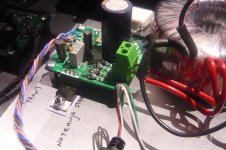
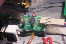
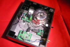
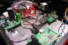
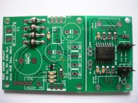
Hi guys! I just wanted to share with you my project. I came up with the idea to supply my ODAC with shunt regulator, I know this isn't anything new and that this has tried somebody before me.
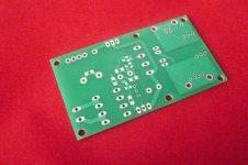
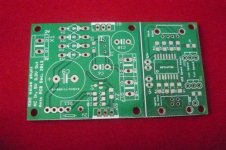
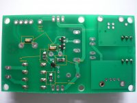
Schematic for regulator was taken from salas and modified a bit, instead of 2SK170 I used BF862 and also power mosfets have been changed. The board is designed so that the isolator part and regulator can be separated if needed, I managed to make it to fit dimensions 75mm*43mm.
I made some measurements on scope and I couldn't see any unusual behavior, I hope I will source better scope and then post measurements.
With this device I have gained even better sound, now I have more dynamics and details have become more clear. 😀
BR,
Ales
Attachments
-
 usb isolator (7).JPG415.9 KB · Views: 769
 -
sense_shunt_and_isolatr_pcb_bottom.pdf25 KB · Views: 111
-
sense_shunt_and_isolatr_pcb_top.pdf38.5 KB · Views: 146
-
sense_shunt_and_isolatr_scheme.pdf27.6 KB · Views: 347
-
 usb isolator (13).JPG391.4 KB · Views: 308
 -
 usb isolator (12).JPG416.4 KB · Views: 297
 -
 usb isolator (11).JPG417.2 KB · Views: 702
 -
 usb isolator (10).JPG467.3 KB · Views: 719
 -
 usb isolator (9).JPG388.2 KB · Views: 728
 -
 usb isolator (8).JPG391.7 KB · Views: 742
Iccs measurments
I did some measurements to determine Iccs from IRF9610, maybe somebody will find this info useful.
Rccs (ohm) Iccs(mA)
8,2 248
6,8 288
5,6 339
5,1 360
4,7 388
3,8 452
3,2 509
I didn't go any further than this as USB devices shouldn't use more than 500mA.
BR,
Ales
I did some measurements to determine Iccs from IRF9610, maybe somebody will find this info useful.
Rccs (ohm) Iccs(mA)
8,2 248
6,8 288
5,6 339
5,1 360
4,7 388
3,8 452
3,2 509
I didn't go any further than this as USB devices shouldn't use more than 500mA.
BR,
Ales
Hi mravlca
Could you provide some informations about :
1° - Electrolytics caps lead spacing
2° - P1 trimmer value, 500R ?
3° - Values for 3.3 & 5.0V Output
4° - SMD 100nF (1206) : mlcc type ?
I've noticed that R11 (Rccs) value sets current amount (Iccs).
Thank you for your answers, sorry for my noob questions 😉
Regards
Phil
Last edited:
Nice job!
Do you have a line input on your PC? Any chance of posting RMAA measurements comparing with and without the isolation?
Do you have a line input on your PC? Any chance of posting RMAA measurements comparing with and without the isolation?
Hi mravlca
Could you provide some informations about :
1° - Electrolytics caps lead spacing
2° - P1 trimmer value, 500R ?
3° - Values for 3.3 & 5.0V Output
4° - SMD 100nF (1206) : mlcc type ?
I've noticed that R11 (Rccs) value sets current amount (Iccs).
Thank you for your answers, sorry for my noob questions 😉
Regards
Phil
Hi Phil,
1° C9 7.5mm*16mm Panasonic FC 4700uF 16V can fit here, C6 & C10 5mm*10.5mm these two caps are a bit overkill in size
2° P1 has a value of 500ohm
3° I will test with my board and report it
4° X7R 50V
Nice job!
Do you have a line input on your PC? Any chance of posting RMAA measurements comparing with and without the isolation?
Thanks! I hope I will be able to do that today.
Thank for your reply.
I need more informations about :
1° - Q3/4/5/6 : SOT23 ?
2° - D5/6/7/8 Green Led 1206 : Voltage / mA / mcd ?
Thanks
Regards
Phil
I need more informations about :
1° - Q3/4/5/6 : SOT23 ?
2° - D5/6/7/8 Green Led 1206 : Voltage / mA / mcd ?
Thanks
Regards
Phil
Last edited:
Thank for your reply.
I need more informations about :
1° - Q3/4/5/6 : SOT23 ?
2° - D5/6/7/8 Green Led 1206 : Voltage / mA / mcd ?
Thanks
Regards
Phil
1° Yes, SOT-23.
2° 2.1V/ 20mA/ mcd->birghtness isn't important
BR,
Ales
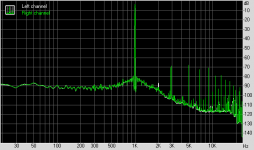
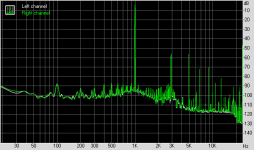
RMAA test
I did some tests. As you can see there is difference between two measurements. 2nd picture is THD using USB isolator and 3rd picture is ODAC only. I believe that with better sound card we could see even bigger difference.
BR,
Ales
I did some tests. As you can see there is difference between two measurements. 2nd picture is THD using USB isolator and 3rd picture is ODAC only. I believe that with better sound card we could see even bigger difference.
BR,
Ales
Attachments
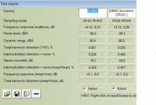
Definitely. I'm guessing you are using an onboard line input with these measurements?I believe that with better sound card we could see even bigger difference.
Definitely. I'm guessing you are using an onboard line input with these measurements?
Yes. It is the only option I have.
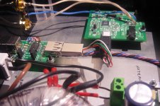
Hi, can I put Q1 and Q2 on the same heatsink or they need to be isolated?
They need to isolated.
BR,
Ales
- Status
- Not open for further replies.
- Home
- Source & Line
- Digital Line Level
- USB isolator with shunt regulator