I am designing 1W Audio Amplifier with mute and volume control which allow end-user to select two different types of frequency response, namely speech and music.The selected choice must be indicated using LEDs (three) which is the end-user has a choice of selecting voice (300hz to 3.3K hz), music or mute mode.
I am a noob in this kind of subject and am now learning. I have come up with the pre amp circuit but wasnt sure how to combine the transistor switching circuit (using SPDT switch- simulated 2 bit signal for mode selection) to the pre amp before connecting to audio amp and speaker (I am using TDA7052A audio amp and 0.5W 8 ohm speaker)
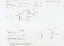
Attached is the draft I have come up with, the left is the pre amp and the right is the circuit for audio amp which I hope both are correct. I left out the transistor switching circuit (require 5V)(suppose to connect to pre amp) as i am not sure how to proceed.
I have left out the calculations as I am still trying to figure out how to calculate as I need the complete diagram first.
Really need your help here .
I have searched through the net and threads but hasnt found anything similar.
Urgent help appreciated!
I am a noob in this kind of subject and am now learning. I have come up with the pre amp circuit but wasnt sure how to combine the transistor switching circuit (using SPDT switch- simulated 2 bit signal for mode selection) to the pre amp before connecting to audio amp and speaker (I am using TDA7052A audio amp and 0.5W 8 ohm speaker)
Attached is the draft I have come up with, the left is the pre amp and the right is the circuit for audio amp which I hope both are correct. I left out the transistor switching circuit (require 5V)(suppose to connect to pre amp) as i am not sure how to proceed.
I have left out the calculations as I am still trying to figure out how to calculate as I need the complete diagram first.
Really need your help here .
I have searched through the net and threads but hasnt found anything similar.
Urgent help appreciated!
Attachments
You don't say where your audio input is coming from, and hence what level its at. If its from a CD player, you certainly won't need the first transistor amplifier - that just adds unnecessary complexity. In fact, if your source is a CD player (2VRMS max output) then you'll actually need something to reduce the level before feeding the TDA7052A, as the datasheet shows this is looking for around 500mV at its input.
R
R
Sorry about the lack of info.
The power supply line to the audio amplifier is a ±12V line from the secondary of the 100KHz switching mode power supply. The input signal to the audio amplifier is derived from the sound demodulated output of the SIF stage. The level of the base-band signal is 250mVp-p at 1kHz. (A function generator is to be used during testing of the circuit).
The power supply line to the audio amplifier is a ±12V line from the secondary of the 100KHz switching mode power supply. The input signal to the audio amplifier is derived from the sound demodulated output of the SIF stage. The level of the base-band signal is 250mVp-p at 1kHz. (A function generator is to be used during testing of the circuit).
So, assuming that the datasheet 500mV is an RMS value the amplifier would like at its input, your 250mV p-p translates to 88mVRMS. So you require a gain of about 6 in your preamp. You definitely don't need the input transistor stage, you can apply the SIF output to the opamp. If that's really a uA741 you've specified there, I suggest you change it to something a little more audio-friendly like a TL071.
Download the datasheet for the TL071 from Texas Instruments' website and you'll find some application circuits shown. You could adopt the first half of the 'Audio distribution amplifier' shown in fig25 as your preamp. Change the 1Mohm resistor shown there to 470k and you'll have about the right gain for this stage.
R
- Status
- This old topic is closed. If you want to reopen this topic, contact a moderator using the "Report Post" button.