I'm working on a Hafler DH-110. This connection to the output connections board is wired as according to the manual. Two pairs of red and green wires with an associated ground wire. One ground is soldered to the board, the other is wrapped around its pair. Why run the second ground if it won't be connected? What benefit does this wiring scheme serve?
Attachments
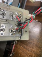
I think the black wire is supposed to be connected on both. Looks like its been modified I'd expect the wiring to be screened (although not really needed for a low impedance output).
I'm assuming red and green are the two channels and black is the ground?
Is the ground on the connector PCB actually commoned for the top and bottom rows, its not clear from the photo?
I'm assuming red and green are the two channels and black is the ground?
Is the ground on the connector PCB actually commoned for the top and bottom rows, its not clear from the photo?
- Home
- Design & Build
- Construction Tips
- Run a ground wire, but not connect it?