Hey folks, I've read some NP articles and other instructions on wiring passive attenuators, and I've built amplifiers and preamplifiers before. I've used the search function and still haven't found the answer I'm looking for so I'm asking here. Usually when this happens I just don't have the vocabulary to search properly, so thanks in advance for your patience.
So I'm wiring an Alps RK27 100k audio potentiometer as a simple passive attenuator because it's useful to have around. With the DIYAudio RK27 breakout board, the wiring is inline like this:
My questions is... why? Why is it wired like this?
Why not wire things up like a variable resistor to ground like at the front end of an amplifier input like this:
Wondering if someone can explain the design elements behind this instead of just "wire this here".
Thanks for helping me learn.
Attachments
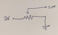
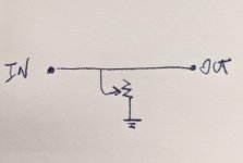
In the first case you tap the divided signal voltage. In the second case you are connecting the input straight to the output so nothing will be attenuated (unless the extra resistance to ground simply pulls down the signal coming in, which may not be how it was intended to be used and may cause distortion.)
At low volumes you will short your source and possibly burn out the attenuator.
This is regarding the variable resistor to ground scheme? Can you explain this a little more?
In the first case you tap the divided signal voltage. In the second case you are connecting the input straight to the output so nothing will be attenuated (unless the extra resistance to ground simply pulls down the signal coming in, which may not be how it was intended to be used and may cause distortion.)
I'm building an F5, which has input resistors at the value 4.75k. If I understand correctly, you're saying it's still the path of least resistance for the signal to go through this input resistance than through the variable R to ground?
If you consider your source as a Voltage source then you shouldn't be trying to short it to ground to make it do things. Stay within the recommended load and if you must change things you'd begin with a series element.
Ok I can work with this. Sounds like I need to read up on how voltage sources work.
I might be back here in a little while to ask a few more questions after I do some independent work.
Thanks for taking a minute with me.
My questions is... why? Why is it wired like this?
Simply because it's a variable voltage divider.
You want a fractional element of the input voltage, a voltage divider is what you use.
Simply because it's a variable voltage divider.
You want a fractional element of the input voltage, a voltage divider is what you use.
This seems to make sense intuitively. I was thinking in terms of subtraction. Instead I should reframe to terms of division.
Good stuff.
Voltage sources should never be shorted, that's how to fry electronics (although a decent preamp will tolerate it OK, some circuits might not.)
The second circuit will act as a distortion generator, not a voltage divider. Overloading the preamp will make it distort a bit, then more, as well as eventually dropping in level before knocking it out on hitting the end-stop.
Typical audio equipment has output impedances in the range <100 ohms to 1k or so, and input impedances in the range 10k to 50k. This means you won't lose signal level when connecting them direct (a 50100:50000 ohm divider is basically 1:1).
Add a 10k log pot between the devices as a divider and you'll get a reasonable attenuation function without overloading the source or adding much noise, and it will be seen as at most 2k5 source impedance by the load and as 10k by the source.
In general active volume controls perform better though, allowing some gain as well as attenuation, and are less dependent on the incoming and outgoing impedances. Its normal for the preamp to provide this rather than make you have yet another device in the chain.
The first picture is as the usual front end of an amplifier.
It is however more usual to draw the schematic with the resistor zig-zag vertically. While looking for a ready drawn schematic I found this -
Amplifier volume and loudness controls.
Read the section 'Volume Control'. No point in me re-stating it.
Your second schematic, when set at minimum volume, you have a dead short to ground.
I was thinking in terms of subtraction. Instead I should reframe to terms of division.
Voltage divider - Wikipedia
Hey folks, I've read some NP articles and other instructions on wiring passive attenuators, and I've built amplifiers and preamplifiers before. I've used the search function and still haven't found the answer I'm looking for so I'm asking here. Usually when this happens I just don't have the vocabulary to search properly, so thanks in advance for your patience.
So I'm wiring an Alps RK27 100k audio potentiometer as a simple passive attenuator because it's useful to have around. With the DIYAudio RK27 breakout board, the wiring is inline like this:
My questions is... why? Why is it wired like this?
Why not wire things up like a variable resistor to ground like at the front end of an amplifier input like this:
Wondering if someone can explain the design elements behind this instead of just "wire this here".
Thanks for helping me learn.
In first typical volume pot, signal source will see always constant resistance, which is good.
In second example, you are shorting the signal source to the ground. No signal source likes it. Was never designed to drive zero ohm, or at low volume just few ohms. Line source likes constant load of few kohm or more.
But do not listen to logic, do what pleases you. Why dont you just skip the amplifier all together, if your signal source can drive few ohms.
.But do not listen to logic, do what pleases you. Why dont you just skip the amplifier all together, if your signal source can drive few ohms.
adason, I didn't know, that's why I asked. I'm under 30 and my background is not in electronics.
You'll have to know some basic electronics (but more than you can discuss here) to understand.
There are lots of introductory electronics texts. This one is in the public domain.
https://www.pearl-hifi.com/06_Lit_A...Vol_16/Sec_51/4420_The_Art_of_Electronics.pdf
There are lots of introductory electronics texts. This one is in the public domain.
https://www.pearl-hifi.com/06_Lit_A...Vol_16/Sec_51/4420_The_Art_of_Electronics.pdf
Last edited:
You'll have to know some basic electronics (but more than you can discuss here), to understand.
There are lots of introductory electronics texts. This one is in the public domain.
https://www.pearl-hifi.com/06_Lit_A...Vol_16/Sec_51/4420_The_Art_of_Electronics.pdf
Thanks for adding the link, I'll add this to my reading list. I am willing to invest some time and energy.
Concentrate on the initial few sections of chapter 1. The rest can wait.
It looks like the above PDF has the first chapter redacted. In case anyone is, like me, interested in learning the fundamentals, it looks like this 3rd edition is fully represented (although not ctrl + f searchable): [deleted]
Last edited:
Deleted. Thanks for the heads up.The third edition is not public domain, and posting a link to it is against forum rules.
- Home
- Design & Build
- Construction Tips
- Wiring a passive attenuator - questions about the "why"