Afternoon all.
I'm looking for a little help concerning the crossovers in my Polk Audio S55 speakers. I recently purchased replacement caps and resistors and would like to point-to-point wire the crossover with the new parts. (The board has some damage.) However, I don't feel comfortable reverse-engineering the crossover schematic for fear of doing it incorrectly. I know some very basic concepts but not enough to look at the crossover and know what goes where.
As I said, I have the parts and Polk-made crossovers, I just need the proper design. I enjoy learning so if anyone could help me out and work through this I would be much appreciated. I'm also more than willing to compensate anyone for their time and effort.
Thanks all and I look forward to hearing from the community!
That is how you reverse engineer a product: characterize it, dissect it, document it. This all takes work.
General Motors is literally tearing its competition to bits | Ars Technica
General Motors is literally tearing its competition to bits | Ars Technica
It's little different from drawing a map. Oak St connects to Cove St which tees into Bay Street which wanders into Water St. A circuit "map" doesn't even use miles or north/south.
But if that is not what you want to do: fix the damage while leaving the stock parts as much alone as possible; else notate and photograph it as you found it. Damaged PCB can be filled with resin or even modeler's plywood (at least for speaker impedance). Peeled and blistered copper can be replaced with simple copper wire (the width on the PCB is nearly meaningless; wire is better).
But if that is not what you want to do: fix the damage while leaving the stock parts as much alone as possible; else notate and photograph it as you found it. Damaged PCB can be filled with resin or even modeler's plywood (at least for speaker impedance). Peeled and blistered copper can be replaced with simple copper wire (the width on the PCB is nearly meaningless; wire is better).
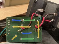
OK. I uploaded a photo that I drew on. It’s a bit amateurish, I know, but here we go.
1. It’s a dual binding post speaker so (obviously) it has the two positive/negative ins.
2. On the left are (from top to bottom) woofer, woofer, tweeter. My understanding is Polk calls this a phased array meaning both woofers run in a two-way but roll off differently. I’ve read it could be seen as either a two-way or 3-way crossover. 🤷🏼*♂️
3. Polk specs say the speaker is 8ohm.
4. The blue lines are resistors. Top left is 5W 6.2ohm. Middle is 5W 0.75ohm.
5. Yellow are inductors. I don’t know the specs.
6. Green are caps. Top is 22uf 400V. Bottom is 8.2uf 400V.
What’s most confusing to me is which component connects to which. I can figure out a few of the more obvious connections but the others I just can’t wrap my head around. Plus, the dual binding post really sends me sideways.
Anyway, any help with what connects to what so I can toss this board and simply connect the components would be great. Thanks!!
Attachments
Other (component) side photo please...
See if you can find data in Philips or here, the crossover circuits for multi way speakers are fairly common, only the individual ratings vary.
Also, the above photo without your markings, at first glance it does not seem damaged.
Also, what made you decide it was damaged or needed work?
Disconnect the drivers (speakers) from the circuit, and use a meter to measure the resistance, tweeters may show open if piezo type, don't worry about those.
Last edited:
The tweeter is connected separately to the amplifier?
If not, please make the drawing again, as if the three elements are connected to the same terminals.
It is tweeter, mid range and woofer, also sometimes sub woofer.
And some schemes use more than 4 to 5 elements connected to the same input. But not relevant here.
If not, please make the drawing again, as if the three elements are connected to the same terminals.
It is tweeter, mid range and woofer, also sometimes sub woofer.
And some schemes use more than 4 to 5 elements connected to the same input. But not relevant here.
Last edited:
First let me say thank you for your help. I’m really appreciative!
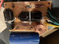
As for the board, I removed the stock components, replaced them with the new ones, and the speakers just didn’t work. At first glance, I thought I may have burned the board because I was a bit heavy-handed with the soldering iron. (See pic) So first I tested the components. Resistors read proper ohms and the caps read OL off the board which I’m told tells me they aren’t shorted. So then I tested the board with my multimeter where one of the caps is designed to sit and I got at .9 (or something close) milli-ohms response, and not OL, which I’m told means that part of the board is shorted. At that point I stated to think I may have damaged the board elsewhere and should try and connect the components point-to-point and disregard the board entirely.
As for the board, I removed the stock components, replaced them with the new ones, and the speakers just didn’t work. At first glance, I thought I may have burned the board because I was a bit heavy-handed with the soldering iron. (See pic) So first I tested the components. Resistors read proper ohms and the caps read OL off the board which I’m told tells me they aren’t shorted. So then I tested the board with my multimeter where one of the caps is designed to sit and I got at .9 (or something close) milli-ohms response, and not OL, which I’m told means that part of the board is shorted. At that point I stated to think I may have damaged the board elsewhere and should try and connect the components point-to-point and disregard the board entirely.
Attachments
Yes, for bi-wiring. Presumably there are post jumpers.The tweeter is connected separately to the amplifier?
It also called 2.5 wayOn the left are (from top to bottom) woofer, woofer, tweeter. My understanding is Polk calls this a phased array meaning both woofers run in a two-way but roll off differently. I’ve read it could be seen as either a two-way or 3-way crossover.
If you have a pair, use the PCB from other speaker as a reference.I tested the board with my multimeter where one of the caps is designed to sit and I got at .9 (or something close) milli-ohms response, and not OL, which I’m told means that part of the board is shorted.
Yes, for bi-wiring. Presumably there are post jumpers.
Yes, I currently have them bi-wired because the post jumpers are junk.
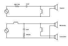
Please correct me if I made any mistakes
Thanks again for this! I’m going to lay this out today and see if it works. If it doesn’t, clearly something is off with one of the components. I’ll send a pic when it’s done.
Well all is complete and things went swimmingly. I can tell the differences already with the most noticeable being the separation between instruments that I didn’t hear before. Everything sounds less muddled. Thanks again for everyone’s help and suggestions. I’ll be sure to stay connected to the board going forward!
Your board (pic post 10) does look rather blackened.
however, the board is heavily plastered with some sort of glue (to secure the components).
It may be the glue that has burnt and so a bit of cleaning and scraping might resolve the issue.
How did you resolve?
Point to point?
Any pictures?
however, the board is heavily plastered with some sort of glue (to secure the components).
It may be the glue that has burnt and so a bit of cleaning and scraping might resolve the issue.
How did you resolve?
Point to point?
Any pictures?
So I have had my Polk s55 for about 2 years and I have been trying to figure out what it is that was not right with the sound. I even had my hearing tested as I am 58 and thought the years of abuse may be causing me to have a problem besides the tinnitus in both ears. Well my ears checked out ok and I can hear even in the range of the high pitch ringing. So I checked everything and even brought a 2 channel yamaha integrated amp with A and B speakers. I bi amped the speakers and still mid range instruments were buried even using a 16 band EQ. So I decided the best thing to do was modify the crossover in the s55's.
I ordered Jantzen 33uf to replace the 22 uf and 6.8 uf to replace the 8.3 uf. Well while I am waiting for them to arrive I decided to just remove the cap for the woofers to make them full range speakers and wow the midrange I was looking for showed up. The other issue I have with the sound is the Tweeters are too bright and loud. I will now just put a resister undetermined value in series with the tweeter to lower its volume and hopefully remove the harshness. I will use the 33UF on the lower woofer in series with the speaker and leave the upper woofer full range. I think this may solve my issues with the sound. I looked at many different speakers of mid range quality like the polk and found them to be the best to my liking in the demo rooms however all the speakers seem to be harsh to my hearing. I believe the lack of mid range is probably due to the idea that these should be used as part of a 5.1 or atmos set up and the center channel would be the Mids. I didnt want a 5.1 amp as I am mostly using this to play from a turntable. Well happy tweaking and remember dont do anything that you dont understand and always be prepared to buy new stuff if you blow up your current equipment by changing parameters.")
I ordered Jantzen 33uf to replace the 22 uf and 6.8 uf to replace the 8.3 uf. Well while I am waiting for them to arrive I decided to just remove the cap for the woofers to make them full range speakers and wow the midrange I was looking for showed up. The other issue I have with the sound is the Tweeters are too bright and loud. I will now just put a resister undetermined value in series with the tweeter to lower its volume and hopefully remove the harshness. I will use the 33UF on the lower woofer in series with the speaker and leave the upper woofer full range. I think this may solve my issues with the sound. I looked at many different speakers of mid range quality like the polk and found them to be the best to my liking in the demo rooms however all the speakers seem to be harsh to my hearing. I believe the lack of mid range is probably due to the idea that these should be used as part of a 5.1 or atmos set up and the center channel would be the Mids. I didnt want a 5.1 amp as I am mostly using this to play from a turntable. Well happy tweaking and remember dont do anything that you dont understand and always be prepared to buy new stuff if you blow up your current equipment by changing parameters.
Well I replaced the 22 uf with a 33 uf and the 8.2 with a 6.8 uf and now I am happy with the sound as I raised the cutoff for the woofer/mids and also raised the FR of the tweeter so less sound is being produced by the tweeter giving a louder mid to low high with a warmer sound overall. I figured if I didnt like it I would just go back to factory capacitors and maybe go shopping for a pair of old school speakers LOLIt is possible one of the drivers was wired wrong phase thus cancelling the mids.
Many crossovers change the phase so one driver has to be wired in reverse.
- Home
- Design & Build
- Construction Tips
- Polk Audio S55 Crossover