Hi Everybody
Today I come with something special and I would like invite anyone to help to give his thoughts and Ideas.
There is no LEADER, everybody can Freely give his input.
The other day we had some conversation going on, at https://www.diyaudio.com/forums/pass-labs/ about the BENEFIT of CLASS A Amplifiers,.
I'm always trying to be honest, but this time it gave me not to a good feedback.
So I think to do against something on these Misunderstandings, that CLASS A is only an EXPENSIVE HEATER for your ROOM in Wintertime, and I'm one who is against, to put CLASS A as Ancient technologies just because I think there is some better.
I promised to design a Control to have the CLASS A SINGLE END which usually Heats up and burns Power for nothing while IDLE, to have them COOL DOWN.
I have the unit running already here at home, and without any other loss I reduced POWER by more than half.
I did not search on the internet if there is already something like that, I just searched for a few Parts to make it happen.
This Circuit can also be used for any other DEVICE / it might need a few modifications.. and that's why I wanted to invite everybody here to help to make it a DIY COMMUNITY DEVICE, where DIYAUDIO.COM is the OWNER. everyone has the right to build without asking, any one has the right to modify the way he likes. the only thing he needs to do, to bring all modification here on this FORUM, so the other can use it as well.
Again the major part of the Circuit already is in use.
To build it will cost between 50 / 100 USD
The Result you get in return is less Power Bills, less heat on your amp and for all lazy guys like me an Automated SHUT OFF, for the DEVICE after a SET TIME.
The device can be set how much Power will pass, and be used.
That's all for the first part. PLEASE GUYS May you want to help to create something good for everybody,
Please Understand this is not FOR ME, because mine is BUILD. and it functions fantastic.
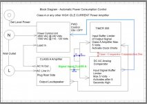
Give you the Block Diagram to EDIT THE WAY you want. It's yours.
There may are some ERROR IS the drawing, just FIX it, no need to ask.
I almost forgot, there is no modification needed on your beloved Amplifier.
It's OPEN SOURCE.!
GIVE ENVIRONMENT A CHANCE and HELP to STOP WASTE POWER WHILE THE AMP IS IN IDLE STAGE.!
My AMP IS BURNING 400 WATTS WHEN IDLE, after using the circuit, it uses below 100Watts for two channels, and it's still loud enough
So no need to miss the good CLASS A SOUND. Pictures will follow.
Thank you and Regards
Chris Hess
Bern Switzerland
Today I come with something special and I would like invite anyone to help to give his thoughts and Ideas.
There is no LEADER, everybody can Freely give his input.
The other day we had some conversation going on, at https://www.diyaudio.com/forums/pass-labs/ about the BENEFIT of CLASS A Amplifiers,.
I'm always trying to be honest, but this time it gave me not to a good feedback.
So I think to do against something on these Misunderstandings, that CLASS A is only an EXPENSIVE HEATER for your ROOM in Wintertime, and I'm one who is against, to put CLASS A as Ancient technologies just because I think there is some better.
I promised to design a Control to have the CLASS A SINGLE END which usually Heats up and burns Power for nothing while IDLE, to have them COOL DOWN.
I have the unit running already here at home, and without any other loss I reduced POWER by more than half.
I did not search on the internet if there is already something like that, I just searched for a few Parts to make it happen.
This Circuit can also be used for any other DEVICE / it might need a few modifications.. and that's why I wanted to invite everybody here to help to make it a DIY COMMUNITY DEVICE, where DIYAUDIO.COM is the OWNER. everyone has the right to build without asking, any one has the right to modify the way he likes. the only thing he needs to do, to bring all modification here on this FORUM, so the other can use it as well.
Again the major part of the Circuit already is in use.
To build it will cost between 50 / 100 USD
The Result you get in return is less Power Bills, less heat on your amp and for all lazy guys like me an Automated SHUT OFF, for the DEVICE after a SET TIME.
The device can be set how much Power will pass, and be used.
That's all for the first part. PLEASE GUYS May you want to help to create something good for everybody,
Please Understand this is not FOR ME, because mine is BUILD. and it functions fantastic.
Give you the Block Diagram to EDIT THE WAY you want. It's yours.
There may are some ERROR IS the drawing, just FIX it, no need to ask.
I almost forgot, there is no modification needed on your beloved Amplifier.
It's OPEN SOURCE.!
GIVE ENVIRONMENT A CHANCE and HELP to STOP WASTE POWER WHILE THE AMP IS IN IDLE STAGE.!
My AMP IS BURNING 400 WATTS WHEN IDLE, after using the circuit, it uses below 100Watts for two channels, and it's still loud enough
So no need to miss the good CLASS A SOUND. Pictures will follow.
Thank you and Regards
Chris Hess
Bern Switzerland
Attachments
Last edited:
I am not quite sure about what this is about. I believe you are proposing to develop an automatic on/off switch that switches on if there is an audio signal applied to the input, and switches off after a while if/when there is no audio signal. This is nothing new under the sun, but I'll admit that I recently was looking for such a board, and it wasn't easy to find one. Still, an Arduino and a relay would do the trick quite easily...
On another note, if you want a community project to be successful, I would be surprised if this would work with "no leader". Someone has to define the design goals and make decisions along the way.
On another note, if you want a community project to be successful, I would be surprised if this would work with "no leader". Someone has to define the design goals and make decisions along the way.
There is more than that.
And yes it is similar to what you wrote.
At present time my class a is running for 2.5 Hours, right now Temp shows 44Degrees. after almost 3hours of running
Usually it would heat up to 80degrees at the Ventilated heat sinks after 20 minutes. and then of course because of Heat Control stay at that level.
This Amplifier has following specs.
V+-Rail 37.5 Volts
RE 10 Ohm, this creates an IDLE CURRENT of 3.7Ampere but normally i use 7.5 Ohm so then it's a mere 37.5:7.5= 187.5Watts HEAT
Now at present time I use with that circuit a VRAIL +- 20 Volts
20:10= 2 * 20 = 40 Watt channel and not 187.5 WATTS that's 147.5 Watts less heat /channel. So the Electricity bill will show less charge..
This is what it is about
The Power module is sold by Reichelt.de for 19.00 Swiss.
Then all it is timed, say if the amp isn't switched off or has no signals output fpr ,more than and this is adjustable, 0- 20 minutes then it will cut down power so much as has been set by the USER. it will start up after a signal enters the Input of the POWER AMP for more than 5 seconds. again to the amount power which has been set by the user
And it should been working for almost any amp.. also for that Pass Amp you have..I tested it on several amplifiers,, A and AB
You are welcome
Everyone is welcome
Last edited:
I am not quite sure about what this is about. I believe you are proposing to develop an automatic on/off switch that switches on if there is an audio signal applied to the input, and switches off after a while if/when there is no audio signal. This is nothing new under the sun, but I'll admit that I recently was looking for such a board, and it wasn't easy to find one. Still, an Arduino and a relay would do the trick quite easily...
On another note, if you want a community project to be successful, I would be surprised if this would work with "no leader". Someone has to define the design goals and make decisions along the way.
Anyone can be leader..let the community decide who it will be.
If I understand correctly:
you have an amplifier designed for supply rails +- 37.5V and consuming 187.5W per channel.
You run the amplifier at +- 20V and consumption drops to 40W per channel.
So your new 'efficient' set-up is still consuming 80W for a stereo pair.
You have a long way to go to save the planet.
I measured a class D amp running from a 20V laptop supply and I couldn't get the current draw above 1 amp playing really loud.
That's 20W for a stereo amp, less at normal listening levels.
Try explaining to a Polar Bear why you need to burn 80W in your amplifier.
you see it's not about this 40 watts, it's about with this we can shut down completely if the amp is not in use. this is also possible..
I have a bad habit, to sleep while listening to say a record, because I do not like nasty sound like out of cola can. and when the record has finished then the AMP is still running, so I think, when it's shutting down, after a certain time, then it's using less power than your laptop Supply, Satisfied?
Have you ever heard this one.,,. they have eyes but they don't see, they have ears but they don't hear,, shall I go on?
But you should never compare a Class D with a CLASS A, it's no MATCH.. it's about the same as you compare AM and FM. Just because you can not hear the Difference in sound doesn't mean that there is no difference. With this I mean the CLASS A is the FM.
Second part of it is that CLASS A you can hear on a level of under 1 Watt, and you have the full spectrum of the sound.
And third part is, better start to do something with low efficiency than nothing.
Just complaining and doing nothing is not the way to go..
But this is in fact so common.
The Polar bear doesn't speak Swiss, nor English German or Chinese french Italian, so hard to explain. When you stop to use up 20 Watts on your AM then I stop to use my CLASS A.
BTW the topic here is how we can achieve a better power to performance RATIO on CLASS A this is actually what I mean.
And I'm happy that you are satisfied with your class D, same as I am with the CLASS A, but this is not the discussion here, this we had last week over at pass labs forum.
Unless you do not use any electricity or other kind of energy, or you might mining Bitcoins at home and stopping that, so, the Discussion is how we can get a better ratio, not to shut down, and better a long way than no WAY.
As I said everybody is welcome to help, that we can do something to prevent using up power when a class a or also a class ab amp is in idle stage. I know it is sometimes hard to understand others, but here this is the discussion about because otherwise there is your way, which in my eyes is NO WAY.
Last edited:
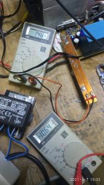
This are original Pics from DUT
View attachment 940414 I think people are not really interested in changing anything in this matter..
Still I think that it's worth it to go one in this matter.
Soon I will post PCB Layout BOM and specification here.,
then it's on each individual here to decide, what could be done.
I'm not a wealthy man, and also not one of these Green Ones, and to old to change my way of life. But here it is the same as everywhere.
Saving just a little energy everyday, in the end it will be a big MASS, if there many do this, to save, and still have " expected live Quality."
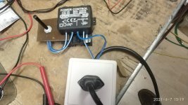
Here, we start with the Power Module. it's a Triac Switched Module with Named:
Kemo Power Control from Germany - Price is 19 Swiss Francs, which equals about 18 Euro or 19 Dollar.
Check out the Picture. And can be ordered by Reichelt.de
This can be extended by some control unit, so it's actually Low Voltage controllable.
Right now I use this in manual mode, 46% but the result is overwhelming.
Till now the Negative side is the switch on Noise, if Circuit is already running, and then switching on the Power Amp.
But this is a thing of fine tuning.
Timer is in work as well as the compartor. At present time I use this in manual mode.
But it already does it job great. Building the control Timer and Sensor unit right now.. so it will take a few days to test. It is according to my drawing.
Again, I think there might be controllers out there doing that job, but then I don't understand why nobody uses them.
So, I not use any schematics which are to find on the Internet, but searched for the POWER CONTROLLER and now building the other parts so I can use it with my Power Amp in Automatic Mode. And I can assure that Manual Mode works.,
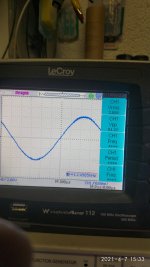
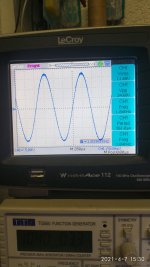
As you can see the Amp works with a Voltage as low as 25% of the one which the amp was designed for.
The last Pic and the second Pic should be viewed togehter as this is with activated Power Control @1 Watt output of the Amp @4 Ohms with here 1/3rd Power on the Transformers.
View attachment 940414 I think people are not really interested in changing anything in this matter..
Still I think that it's worth it to go one in this matter.
Soon I will post PCB Layout BOM and specification here.,
then it's on each individual here to decide, what could be done.
I'm not a wealthy man, and also not one of these Green Ones, and to old to change my way of life. But here it is the same as everywhere.
Saving just a little energy everyday, in the end it will be a big MASS, if there many do this, to save, and still have " expected live Quality."
Here, we start with the Power Module. it's a Triac Switched Module with Named:
Kemo Power Control from Germany - Price is 19 Swiss Francs, which equals about 18 Euro or 19 Dollar.
Check out the Picture. And can be ordered by Reichelt.de
This can be extended by some control unit, so it's actually Low Voltage controllable.
Right now I use this in manual mode, 46% but the result is overwhelming.
Till now the Negative side is the switch on Noise, if Circuit is already running, and then switching on the Power Amp.
But this is a thing of fine tuning.
Timer is in work as well as the compartor. At present time I use this in manual mode.
But it already does it job great. Building the control Timer and Sensor unit right now.. so it will take a few days to test. It is according to my drawing.
Again, I think there might be controllers out there doing that job, but then I don't understand why nobody uses them.
So, I not use any schematics which are to find on the Internet, but searched for the POWER CONTROLLER and now building the other parts so I can use it with my Power Amp in Automatic Mode. And I can assure that Manual Mode works.,
As you can see the Amp works with a Voltage as low as 25% of the one which the amp was designed for.
The last Pic and the second Pic should be viewed togehter as this is with activated Power Control @1 Watt output of the Amp @4 Ohms with here 1/3rd Power on the Transformers.
Attachments
Last edited:
Just stay on and read, my friend.. you know that swiss saying " aller Anfang ist schwer" translated into English.. Sometimes a beginning can consist of hard times..Ok, this thread went the wrong way quite quickly, same as the "Is Class A beneficial?" thread. I am out of here.
we will see..
BTW the device produces almost no heat, and I have 2* 750VAC Transformers in Serie with that device.. For the Price a good deal.. The small volume control is "for now" to control the Phase cut which is used to control this unit.
Anway thanks for your input
As an aside, in 2013 I had this wild idea for an amplifier that could with a potmeter be set to class-A, nonswitching class-AB and anything in between. It would feature an LED that would light up for a second if it went into the class-AB regime, so if you wanted to use class A, you could turn up the bias until that LED remained off and use the smallest quiescent current necessary to keep it in A at the volume at which you were listening. I also thought about adding a blind listening feature, so you could convince yourself that you don't hear any difference anyway and use it at its lowest quiescent current from that moment on. I never built it, though.
Amplifier with variable bias that indicates whether it works in A or AB
Amplifier with variable bias that indicates whether it works in A or AB
@MarcelvdG You should have followed that path,
Thanks for your input, it has some nice Idea in it..
My Amplifiers are designed to work from +- 30 - 48 Volts
The next one which is already calculated and circuit is drawn, uses for the Input +- 63 Volts and for the Output +-42 Volts or more.. But According to a very smart Man, who told me to Set voltage higher so it will be as high as +-63 Volts also for the MAIN STAGE of the Amplifier.
With Reducing the RE it will be possible to achieve a better Power to Performance Ratio.
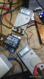
That Amp which we can see in the picture usually runs on 37 Volts with 10 Ohms RE this makes then 3.7Ampere as Idle.
If we look at the Picture where 1 Watts output power is shown the RAIL Voltage is down to +- 10 Volts with 1.4Amps Current of Idle, making a 14 Watts Input Power. and still delivering 2.88 Volts RMS which is 9.12 Volts peak to peak, and this is 81:4= 20 Watts Peak to Peak more than enough to have in the living room, but the major thing is, that this runs in PURE CLASS A. So it's very near to Class D in Power Consumption but Light Years ahead when listening to the sound.
And how is it done?
With this Power Control Unit I'm trying to create.
Idle depends alone on RE
Thanks for your input, it has some nice Idea in it..
My Amplifiers are designed to work from +- 30 - 48 Volts
The next one which is already calculated and circuit is drawn, uses for the Input +- 63 Volts and for the Output +-42 Volts or more.. But According to a very smart Man, who told me to Set voltage higher so it will be as high as +-63 Volts also for the MAIN STAGE of the Amplifier.
With Reducing the RE it will be possible to achieve a better Power to Performance Ratio.
That Amp which we can see in the picture usually runs on 37 Volts with 10 Ohms RE this makes then 3.7Ampere as Idle.
If we look at the Picture where 1 Watts output power is shown the RAIL Voltage is down to +- 10 Volts with 1.4Amps Current of Idle, making a 14 Watts Input Power. and still delivering 2.88 Volts RMS which is 9.12 Volts peak to peak, and this is 81:4= 20 Watts Peak to Peak more than enough to have in the living room, but the major thing is, that this runs in PURE CLASS A. So it's very near to Class D in Power Consumption but Light Years ahead when listening to the sound.
And how is it done?
With this Power Control Unit I'm trying to create.
Idle depends alone on RE
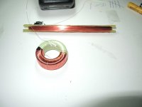
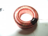
Winding a Toroidal Transformer, to use with Power Controller
Hi all DIY guys and ladies if there are any.
It' s been a few days since I started this thread here. In order to build this Power Controlller we need some special Sensors, which will always give true feedback of the Amplifiers Input / Output state so the circuit can cut down power and or switch the AMPLIFIER off in any of this states. Some parts we have to DIY and here I show one of this components.
It's a small toroid Transformer which when full load Ouput power appears at the Speaker binding post, does change this ouput Voltage to a steady DC voltage, which we can use to work with and send to timer and controller.
In the same time where there is no Input nor output power then this Smaall toroidal needs to be steady at a high level, But since there is no ouput Voltage at the speaker binding posts we need to invert the signal and this also counts for Input of the amplifier in the same manner. There then we need to sense that Input is low, but with a high Voltage signal.
So we need an AND gate and also a NAND GATE which tells the timer to start measure the Set Time to bring the AMP into " Low Power Stage"controling the power of controlling unit and thus shifts the phase of the LINE Voltage *110 / 240) till the desired Voltage has been reached. And as long there is no Signal at the signal input of the amplifier, keep that AMP in reduced Power stage but as soon a Signal at the input is detected, and this for more than 5 senconds and the signal also appears steady at the output of the AMP, then Power Control will be reset to full power Stage, and the amp delivers full power again
Now this toroidal transformer we need to build by our own. there is a lot of documentation on the internet about how to wind a Toroidal transformer. So I started to do so.
After a few tries I got a way which is in fact easy to do but still time consuming. but if you have any company wind that by machine and only one piece, you will surely pay quite a lot of money.
Anyway there is a big must on that Transformer, it should not load the output but still being accurate between two Voltage Stages, 0 volts and +5 volts because AND and NAND GATES understand only this language.
then also the transformer must amplify the output singnal on the speaker connection binding posts so that only if the speaker output has no SIGNAL reaches 5Volts, in any other state of the Output of the amplifier, the Voltage from that Small toroidal transformer must not exceed 2 Volts. and therefore we wind our own Toroidal Transformer.
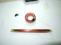
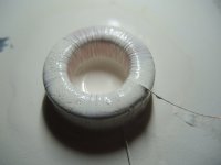
Here are my first tries, and Make sure that if you wind that Toroidal then work as exact as you can. even there is no price to win, but to work flawless we need to set one wire besides the other and try not to jump or create to large air gaps. Air gaps are not welcome at all.
Check out the pictures. and this is really time consuming. then also check out the wire first about Resistance per 1 meter and calulate how much wire you need. To make sure that output Signal of the Speakers are not loaded, so I think 20-50 Ohms for connected output speakers of 4 ohms will do just fine as the load is calculated then by
Transformer X Speaker Resistance : Transformer + Speaker Resistance
this would then be:
30*4=120 Ohms : 30+4 = 3.5 Ohms and if this is not enough close to the desired 4 ohms you still can change that winding up to a higher ohm level.To double the DC Voltage of the output of that Transformer we can switch a DELON Diode circuit behind the rectifier. This will not be a big problem as we do not need high current there. Say 20 - 50 Milliamps will be more than enought to drive the transistor which then in return turns on the TIMER.
I will be back in a few days here again, as soon I'm done with that winding of that toroidal transformer...
The pictures you see are pics showing the Primary Winding done 1/3rd.
Thanks for reading
Regards
Chris Hess
Bern Switzerland
Hi all DIY guys and ladies if there are any.
It' s been a few days since I started this thread here. In order to build this Power Controlller we need some special Sensors, which will always give true feedback of the Amplifiers Input / Output state so the circuit can cut down power and or switch the AMPLIFIER off in any of this states. Some parts we have to DIY and here I show one of this components.
It's a small toroid Transformer which when full load Ouput power appears at the Speaker binding post, does change this ouput Voltage to a steady DC voltage, which we can use to work with and send to timer and controller.
In the same time where there is no Input nor output power then this Smaall toroidal needs to be steady at a high level, But since there is no ouput Voltage at the speaker binding posts we need to invert the signal and this also counts for Input of the amplifier in the same manner. There then we need to sense that Input is low, but with a high Voltage signal.
So we need an AND gate and also a NAND GATE which tells the timer to start measure the Set Time to bring the AMP into " Low Power Stage"controling the power of controlling unit and thus shifts the phase of the LINE Voltage *110 / 240) till the desired Voltage has been reached. And as long there is no Signal at the signal input of the amplifier, keep that AMP in reduced Power stage but as soon a Signal at the input is detected, and this for more than 5 senconds and the signal also appears steady at the output of the AMP, then Power Control will be reset to full power Stage, and the amp delivers full power again
Now this toroidal transformer we need to build by our own. there is a lot of documentation on the internet about how to wind a Toroidal transformer. So I started to do so.
After a few tries I got a way which is in fact easy to do but still time consuming. but if you have any company wind that by machine and only one piece, you will surely pay quite a lot of money.
Anyway there is a big must on that Transformer, it should not load the output but still being accurate between two Voltage Stages, 0 volts and +5 volts because AND and NAND GATES understand only this language.
then also the transformer must amplify the output singnal on the speaker connection binding posts so that only if the speaker output has no SIGNAL reaches 5Volts, in any other state of the Output of the amplifier, the Voltage from that Small toroidal transformer must not exceed 2 Volts. and therefore we wind our own Toroidal Transformer.
Here are my first tries, and Make sure that if you wind that Toroidal then work as exact as you can. even there is no price to win, but to work flawless we need to set one wire besides the other and try not to jump or create to large air gaps. Air gaps are not welcome at all.
Check out the pictures. and this is really time consuming. then also check out the wire first about Resistance per 1 meter and calulate how much wire you need. To make sure that output Signal of the Speakers are not loaded, so I think 20-50 Ohms for connected output speakers of 4 ohms will do just fine as the load is calculated then by
Transformer X Speaker Resistance : Transformer + Speaker Resistance
this would then be:
30*4=120 Ohms : 30+4 = 3.5 Ohms and if this is not enough close to the desired 4 ohms you still can change that winding up to a higher ohm level.To double the DC Voltage of the output of that Transformer we can switch a DELON Diode circuit behind the rectifier. This will not be a big problem as we do not need high current there. Say 20 - 50 Milliamps will be more than enought to drive the transistor which then in return turns on the TIMER.
I will be back in a few days here again, as soon I'm done with that winding of that toroidal transformer...
The pictures you see are pics showing the Primary Winding done 1/3rd.
Thanks for reading
Regards
Chris Hess
Bern Switzerland
Attachments
- Status
- This old topic is closed. If you want to reopen this topic, contact a moderator using the "Report Post" button.
- Home
- Design & Build
- Construction Tips
- What's About A DIY Group Production / Join Developement