My application is a capacitive discharge type design. 800vdc.
I am currently using a mechanical switch for initial testing. I charge small 120mm magnets.
I now want to use thyristor for switch.
I googled a lot but i did not get anything that can clearly explain how to use the circuit. How much gate supply should be used and how much gate charge must be used.
I saw many people using KP1500 thyristor for their magnetizer. But never asked them the application circuit.
Any help would be highly appreciated.
Also brothers no theoretical knowledge available here so please explain in very basic english. 😊😊
TRIAC any use?
Magnet Charger
i am using capacitive discharge method so this implementation is not suitable here.
i need to know how to get this thyristor thing to work. Don't wanna purchase a new one.
")
I would be interested to see your circuit.
i am also interested in it if it ever happens
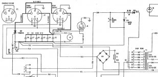
Full circuit attached below.
This one charges 7200uF worth of caps to 340V peak, a real powerhouse
T1 has a tapped secondary, in 35V steps, up to 240V AC so 340V peak charging caps.
First tap makes regulated 6.8V to trigger SCR gate, others allow for different magnetizing coils, from earphones or guitar pickups to tweeters to small speakers to large ones.
Connectors Front or Rear allow for external magnetizing coils, different size and shape according to need.
Plugs not only connect coils, but also have a pair shorting terminals below, as a safety feature, if unplugged a relay can not turn on and allow for capacitor bank charging.
R3 and R4 protect thyristor gate and quickly dscharge trigger capacitor, which then will take sometime to recharge and be able to charge another magnet, this to pause magnetizing operations so as no to overheat magnetizing fixture
coil which takes a beating.
There´s not much more to it, as Turk 182 said working principle is basic.
Almost forgot: M1 is a voltmeter to check charge status.
Attachments
Full circuit attached below.
This one charges 7200uF worth of caps to 340V peak, a real powerhouse
T1 has a tapped secondary, in 35V steps, up to 240V AC so 340V peak charging caps.
First tap makes regulated 6.8V to trigger SCR gate, others allow for different magnetizing coils, from earphones or guitar pickups to tweeters to small speakers to large ones.
Connectors Front or Rear allow for external magnetizing coils, different size and shape according to need.
Plugs not only connect coils, but also have a pair shorting terminals below, as a safety feature, if unplugged a relay can not turn on and allow for capacitor bank charging.
R3 and R4 protect thyristor gate and quickly dscharge trigger capacitor, which then will take sometime to recharge and be able to charge another magnet, this to pause magnetizing operations so as no to overheat magnetizing fixture
coil which takes a beating.
There´s not much more to it, as Turk 182 said working principle is basic.
Almost forgot: M1 is a voltmeter to check charge status.
nice one but too much complicated for a newbie.
mine charges at 1600v 4000uf. i like to keep it very simple. only thing is i want to use SCR for firing circuit and i dont get how to keep the cycle going for magnetization as when using DC SCR don't auto disconnect on removing the gate current.
Also i am doing a bit research on GTO thyristors. What do you say can it be used for this application?
I will be lowering my voltage to 800v and increasing the caps to 10000uf after introducing SCR.
To "charge" magnets;
Calculate how many Joules of energy will be required and charge up the capacitor/s accordingly.
The coil has the charged voltage discharged through it.
No switching off required as the voltage is set, the capacitance is a known quantity and the stored energy, expressed in Joules, is released across the coil. As the magnetize button is depressed, the charging system is disconnected, the charge voltage is removed, through the firing of ther thyristor's gate, allowing complete discharge of the capacitors and the thyristor will release upon low/no voltage across it.
This system has been in use for many years and is very successful and simple.
Last edited:
Full circuit attached below.
This one charges 7200uF worth of caps to 340V peak, a real powerhouse
T1 has a tapped secondary, in 35V steps, up to 240V AC so 340V peak charging caps.
First tap makes regulated 6.8V to trigger SCR gate, others allow for different magnetizing coils, from earphones or guitar pickups to tweeters to small speakers to large ones.
Connectors Front or Rear allow for external magnetizing coils, different size and shape according to need.
Plugs not only connect coils, but also have a pair shorting terminals below, as a safety feature, if unplugged a relay can not turn on and allow for capacitor bank charging.
R3 and R4 protect thyristor gate and quickly dscharge trigger capacitor, which then will take sometime to recharge and be able to charge another magnet, this to pause magnetizing operations so as no to overheat magnetizing fixture
coil which takes a beating.
There´s not much more to it, as Turk 182 said working principle is basic.
Almost forgot: M1 is a voltmeter to check charge status.
JMFahey, can you please upload complete circuit diagram as it appears like some part is missing.
I rechecked the diagram but got a little confused. As far as i know R3 and R4 should not be connected if there is external supply of 6.8volts applied.
Can you please clear my confusion?
To "charge" magnets;
Calculate how many Joules of energy will be required and charge up the capacitor/s accordingly.
The coil has the charged voltage discharged through it.
No switching off required as the voltage is set, the capacitance is a known quantity and the stored energy, expressed in Joules, is released across the coil. As the magnetize button is depressed, the charge voltage is removed, through the firing of ther thyristor's gate, allowing complete discharge of the capacitors and the thyristor will release upon low/no voltage across it.
This system has been in use for many years and is very successful and simple.
can you give me a firing circuit for SCR?
discharge a large bank of caps through a magnetizing coil simple enough,no?
Well, that's what I thought but the op suggested that he was using a different method to this (re posts 3 & 4).
The difference would appear to be in the charging voltage (800V vs 60V).
Well, that's what I thought but the op suggested that he was using a different method to this (re posts 3 & 4).
The difference would appear to be in the charging voltage (800V vs 60V).
No matter what the voltage, principle will remain the same.
- Home
- Design & Build
- Construction Tips
- Need help for speaker magnet magnetizer