Gentlemen, the right channel of my AUDIO Agile Step AMP is broken.
There is only hum coming out of the right speaker, and when I look at the right channel with my scope, I see the input signal (a simple 1 KHz sinus)
oscillating around 0 VDC.
I do not have any documentation concerning the STEP AMP.
Moreover: the AUDIO Agile company does not exist anymore, and I do not find a communication ID (f.e. EMail) of its owner (?),
Mr. Björn Langlie, in the INTERNET.
Is anyone of you able to support me repairing the STEP AMP?
It would be best, if the one who says: "I will do (assist you, repair) it" lives in EUROPE.
Many thanks and best regards - keep safe from CORONA - Rudi_Ratlos
Attachments
Area wise the UK has been made part of Europe as far as most big enterprises are concerned .
Nice looking amplifier , yes its very hard to find a schematic for it .
You say-quote- the input signal of 1KHz is hovering around ---0vDC ?
Do you mean -1- that its hovering around 0 v AC as its sinusoidal ?
Or-2- a very small 1KHz signal is hovering around DC (no signal ).
In any case what you are seeing is that same signal is reaching the output via the power supply rather than via the signal path, you probably have short circuited output devices , I have seen this before .
Of course it could be something else but that would be my first port of call.
What are the numbers of the output devices, ? If the Output devices from either side would be broken then you wouldn't have any sound on the amplifier.,
This seems to be a CLASS AB AMP so, Speaker protection would jump in, if the amp hasn't a speaker protection then the loudspeaker would burn.
I think the line drive, after the selector is bad. either this long CHIP on the right side or one of the transistors,,
Follow with the scope on that side if you can see the 1KHZ trace. set to 1 volt and then compare channels, this is not an exotic Circuit, I think, just step by step and you will find it. I see the layout is centered so it should not be that hard with a working channel to find what exactly is broken.
Check if this condition are met.
Output DC Voltage must be 0Volt. or almost 0
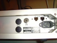
I see a headphone JACK at the back, check for continuity.
insert a HEADPHONE and check if you have sound.. I See this many times in my life that the jacks had bad contact..
Insert a 1khz signal and then measure on red and blue wire which run out the Volume control because there is the input of the Power amp. it can be as well a broken volume control.. that's why the hum.It can be anything else but I doubt that it is the Power stage which is the problem
Regards
Chris
This seems to be a CLASS AB AMP so, Speaker protection would jump in, if the amp hasn't a speaker protection then the loudspeaker would burn.
I think the line drive, after the selector is bad. either this long CHIP on the right side or one of the transistors,,
Follow with the scope on that side if you can see the 1KHZ trace. set to 1 volt and then compare channels, this is not an exotic Circuit, I think, just step by step and you will find it. I see the layout is centered so it should not be that hard with a working channel to find what exactly is broken.
Check if this condition are met.
Output DC Voltage must be 0Volt. or almost 0
I see a headphone JACK at the back, check for continuity.
insert a HEADPHONE and check if you have sound.. I See this many times in my life that the jacks had bad contact..
Insert a 1khz signal and then measure on red and blue wire which run out the Volume control because there is the input of the Power amp. it can be as well a broken volume control.. that's why the hum.It can be anything else but I doubt that it is the Power stage which is the problem
Regards
Chris
Chris, thank you very much for your answer and your recommendations, how to go on.
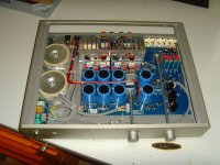
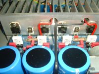
My "Audio Agile Step" amplifier uses pairs of BDW83C(BDW84C) on the output (see image 1).
Have a look at image 2.
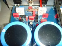
You do not see any tracks, nor do you see any solder-points on the components side of the PCB.
You won't see any tracks on the bottom-side of the PCB either.
I therefore think that the AGILE Step amplifier uses a "more than component-side / solder-side" PCB layout that I will never be able to repair.
I will therefore give up my hope to ever listen to the Audio Agile again, but will bury it on my audio cemetery.
Best regards - Rudi_Ratlos
P.S.: Do not reply to this thread anymore.
My "Audio Agile Step" amplifier uses pairs of BDW83C(BDW84C) on the output (see image 1).
Have a look at image 2.
You do not see any tracks, nor do you see any solder-points on the components side of the PCB.
You won't see any tracks on the bottom-side of the PCB either.
I therefore think that the AGILE Step amplifier uses a "more than component-side / solder-side" PCB layout that I will never be able to repair.
I will therefore give up my hope to ever listen to the Audio Agile again, but will bury it on my audio cemetery.
Best regards - Rudi_Ratlos
P.S.: Do not reply to this thread anymore.
Attachments
Rudi if no copper tracks are visible either on the component side of the PCB nor on the reverse side then you have a "multi-layer board " .
This consists of-
1--an internal signal layer .
2-- an internal ground layer .
3--an external signal layer .
The external signal layer will not show the circuit tracing but just the component holes, its quite a process .
As its dearer than a standard PCB its been done intentionally to obtain more profit in the event of a fault condition by changing the whole board.
I scrolled through the whole process its quite fascinating.
Rudi
Where you are in Germany?
I'm normally every couple months in germany, may next time I come up there I can take a look at,, Don't worry about we will be able to fix that..Mulitlayer boards are also in computers and if someone knowing how an amplifier works then there is no need to see the lines, may one of this multilayer tracks is brocken inside..Does the LED lights up, when power is applied? Compared to the side which works, all it takes is a voltmeter, and measuring at the legs of the transistos.. follow the voltage and you will find the problem. Not seeing tracks is not a problem if you have a working side.Set up a Excel sheet with the number of the transistors, name the legs B C E find the corresponding DATA on the internet in DATASHEET. Then measure the good channel, after that measure the Channel which don't work, note down what you measure.. USE DC Range, 0 - 50 Volts first and then if this scale is too large scale down to 10 volts or what you find appropriate. I can go through this with you step by step, and we will be able to fix that.
Regards
Chris
Last edited:
- Status
- This old topic is closed. If you want to reopen this topic, contact a moderator using the "Report Post" button.
- Home
- Design & Build
- Construction Tips
- Help with broken AUDIO AGILE Step AMP please