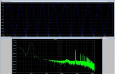
|
Home | Forums | Rules | Articles | diyAudio Store | Blogs | Gallery | Wiki | Register | Donations | FAQ | Calendar | Mark Forums Read |
Class D Switching Power Amplifiers and Power D/A conversion |
|
Please consider donating to help us continue to serve you.
Ads on/off / Custom Title / More PMs / More album space / Advanced printing & mass image saving |
![]() |
|
Thread Tools |
![]() |
#111 |
diyAudio Member
Join Date: Mar 2005
Location: Beta Zeticuly
|
Alright, I spent the better part of today getting re-acquainted with LTspice and I entered the full schematic, created simbols for the parts that weren't in the library (such as the IR2011 driver) and I was able to get it to work.
However, since I've never used LTspice to simulate amplifier efficiency, THD and other things you'd like to know prior to putting the idea to reality I'd like to know how to do this. The following things are of interest to me: - Frequency range, how linear is the amp? - Efficiency, power in vs. power out ratio - THD, how about the distortion? - Carrier frequency, how to find the carrier frequency? - etc. These questions may seem trivial to those of you that have used LTspice for a while but remember I'm new to LTspice, I did work with Spice in school, but that's a different beast and a lot of years ago as well. Any suggestions are most welcome! Best regards, Sander Sassen http://www.hardwareanalysis.com Edit: sloppy spelling and grammar |
![]() |
![]() |
#112 |
diyAudio Member
Join Date: Jan 2001
Location: Germany
|
Is the amp scaleable?
|
![]() |
![]() |
#113 |
diyAudio Member
Join Date: Mar 2005
Location: Beta Zeticuly
|
Yes, why wouldn't it be? Just replace the output MOSFETs with beefier ones and up the voltage and there's no reason why it shouldn't work. Just keep in mind that this design is not yet finalized, hence things will change before I'm happy with it and publish the final schematics and a board layout.
Best regards, Sander Sassen http://www.hardwareanalysis.com |
![]() |
![]() |
#114 |
diyAudio Member
Join Date: Mar 2005
Location: Beta Zeticuly
|
Alright, to keep a long story short. I've modelled my SODFA design in LTspice and decided to have a go at a UcD version of the amplifier as well, hence I took a good hard look at Bruno's AES paper and got to work. The simulations I did with the UcD design in LTspice consistently generated better scores. One of the culprits though is that the carrier frequency is hard to control with a UcD design, yet I managed to lock it down to 400KHz on my UcD design without too much trouble. Below are the screenshots for both designs. They are run with the following commands:
SINE(0 x 10k) (x = 1 for UcD, 0.7 for SODFA) .tran 0 500u 0 1u steady uic .four 10kHz 10 V(OUTPUT) Typical output for both designs is around 28vrms with 1vrms input into an 8-ohm load and both operate at 400KHz carrier frequency, give or take a few KHz. Below you'll also find the THD results clipped from the log files from both designs. In the below images you see in the top left corner the FFT result with 'none' selected for windowing. In the top right 'Hann' is selected for windowing. The magnification of the output is shown in the bottom left and you can clearly see the carrier frequency here. ucd_class_d_002 ![]() sodfa_class_d_001 ![]() ucd_class_d_002 THD Per .tran options, skipping operating point for transient analysis. Changing Tseed to 1e-010 Changing Tseed to 1e-012 Heightened Def Con from 0.0005 to 0.0005 Fourier components of V(output) DC component:0.173333 Harmonic Frequency Fourier Normalized Phase Normalized Number [Hz] Component Component [degree] Phase [deg] 1 1.000e+04 2.672e+01 1.000e+00 174.20° 0.00° 2 2.000e+04 8.681e-04 3.248e-05 109.55° -64.65° 3 3.000e+04 4.190e-03 1.568e-04 -36.04° -210.24° 4 4.000e+04 7.609e-04 2.847e-05 -29.58° -203.78° 5 5.000e+04 3.966e-04 1.484e-05 -94.52° -268.72° 6 6.000e+04 2.910e-04 1.089e-05 158.48° -15.72° 7 7.000e+04 7.928e-04 2.967e-05 131.18° -43.02° 8 8.000e+04 2.310e-04 8.643e-06 137.23° -36.97° 9 9.000e+04 5.948e-04 2.226e-05 -173.89° -348.10° 10 1.000e+05 2.767e-04 1.035e-05 147.85° -26.35° Total Harmonic Distortion: 0.016836% sodfa_class_d_001 THD Per .tran options, skipping operating point for transient analysis. Changing Tseed to 1e-010 Changing Tseed to 1e-012 Heightened Def Con from 5.52581e-005 to 5.52631e-005 Heightened Def Con from 0.000486508 to 0.000486513 Fourier components of V(output) DC component:-0.0286258 Harmonic Frequency Fourier Normalized Phase Normalized Number [Hz] Component Component [degree] Phase [deg] 1 1.000e+04 2.645e+01 1.000e+00 167.79° 0.00° 2 2.000e+04 3.672e-03 1.388e-04 -97.61° -265.40° 3 3.000e+04 1.136e-02 4.294e-04 -56.04° -223.83° 4 4.000e+04 2.805e-03 1.060e-04 -76.36° -244.15° 5 5.000e+04 8.415e-04 3.181e-05 140.66° -27.12° 6 6.000e+04 3.277e-03 1.239e-04 -108.79° -276.58° 7 7.000e+04 3.673e-03 1.388e-04 -88.74° -256.53° 8 8.000e+04 4.050e-03 1.531e-04 -102.67° -270.45° 9 9.000e+04 3.128e-03 1.182e-04 -70.75° -238.54° 10 1.000e+05 2.682e-03 1.014e-04 -78.02° -245.80° Total Harmonic Distortion: 0.054611% Obviously my preference is the UcD as it simulates a lot better and uses fewer components also, and I usually keep with my motto 'keep it simple'. However there's more to this story than just the switch from SODFA to UcD. As mentioned in the first paragraph of this post the one thing that's hard to do with UcD is precisely control the carrier frequency. It is basically controlled by the delay between the in- and output. Below is the principle schematic for a UcD amplifier courtesy of the talented Bruno Putzeys. Bruno's UcD concept ![]() Obviously in the Hypex UcD modules the comparator and MOSFET drivers are exactly matched so that the carrier freqeuncy can be controlled. This however is a balancing act which is hard to follow for the DIY-er, especially if you want to use ICs instead of discrete components. There's a way around this though, as you can simply include a R/C network with the UcD concept and connect that to the comparator's other input. Now you have control over the carrier frequency. Unfortunately doing it that way will shift the hysterisis of the comparator and hence introduce non-linear distortion, so we are faced with a whole new problem. UcD with R/C network ![]() Fortunately that is a problem that can easily be tackled by using a 2nd comparator, see below, and put the R/C network at its input. Hence there's no shift in hysterisis and the carrier frequency can be controlled exactly. I'm modelling this design in LTspice as I write this, so I have not yet drafted a somewhat final schematic, results from the simulation are however promising. Sander's UcD concept ![]() The big advantage obviously is that you can use fast opamps and comparators that are readily available, such as the LT1016 used in the above pictured UcD design without having to exactly match propagation delay in a design to reach a certain target carrier frequency. It can now be simply controlled by adding a second (ultra-fast if you like) comparator with a simple R/C network. Best regards, Sander Sassen http://www.hardwareanalysis.com |
![]() |
![]() |
#115 |
diyAudio Member
Join Date: Sep 2004
Location: Yahoo, USA
|
![]()
Hi there Sander,
You wrote: > I've been trying to properly model my design in > LTspice. Unfortunately I've not used LTspice before, > we used Spice in school but that is almost a decade > ago and thus progress is slow. Hence I would welcome > some feedback if at all possible. Please have a look > at the two below quoted ZIP files which also include > a model for the IR2011 driver (modified from a > IR2110 model). > > I can get both amps to work but I don't know why > efficiency is that low (around 5 to 15% for both) > hence my MOSFETs are being cooked in the simulation. > In reality (got both amps running on the testbench) > they're slightly warm at most, so what's going on > here? As previously mentioned in a private email, your driver model is largely at fault. I am attaching a zip file of a (hopefully) more accurate LTspice model of my own making. Unzip the test, model and symbol files to the same directory that contains your class d simulation schematics. Also, the level shifter (to the driver inputs) in your schematic is lacking any dead time generator. The nominal 5ns or so provided by the IR2011 is not enough to overcome the asymmetry of the MOSFET's four volt gate threshold (relative to the sixteen volt driver supply) to avoid some efficiency killing cross conduction (which actually might enhance amplifier fidelity). By the way, in LTspice, to get the best dynamic range with LTspice's FFT, you should turn off waveform compression and set the transient step size and end time to generate a sufficiently large, evenly distributed power of two of data points. Regards -- analogspiceman |
![]() |
![]() |
#116 | |
diyAudio Member
Join Date: Sep 2004
Location: Yahoo, USA
|
![]() Quote:
1) From within the LTspice schematic editor, open the "Place Component Symbol" dialog box as usual. 2) At the very top of the box click on the down arrow to get the drop-down selection pick list for a new "Top Directory". 3) Choose the folder where your working schematic currently is located and the IR2011 should now appear in the symbol selection area. 4) Select it and place it on your schematic as usual. If desired, you may open the sub schematic (of the IR2011) by right clicking on it from within the top level schematic (your class d design). In this way you can access internal driver nodes during a simulation and plot them with a simple point-and-click (be sure you've enabled save subcircuit node voltages/currents from within the "Save Defaults" tab of the Control Panel). Good luck! -- analogspiceman |
|
![]() |
![]() |
#117 |
diyAudio Member
Join Date: Mar 2005
Location: Beta Zeticuly
|
Much appreciated analogspiceman, the simulation is now up and running, thanks again!
Best regards, Sander Sassen http://www.hardwareanalysis.com |
![]() |
![]() |
#118 |
diyAudio Member
Join Date: Mar 2005
Location: Beta Zeticuly
|
Alright, over the holidays I've been able to try out different topologies (UcD, SODFA, hys. osc.) and have acquainted myself with RightMark Audio Analyzer (RMAA) which allows for frequency reponse, THD, IMD, S/N, etc. measurements using your PC equipped with a good quality sound card.
![]() I've started out with a UcD concept, which is pictured above on the perforated board. It worked, but needed some tweaking to get it to run half decent (R/C in the feedback loop). The SODFA ran beautifully without any tweaks and the same applies to the hys. self oscillator. All of these were modelled and optimized in LTspice prior to trying them out on the breadboard, the carrier frequency is ~400KHz for all topologies. Below you'll find the RMAA plots for all topologies running at ~80-watts/8-ohm at 1KHz. Needless to say I made sure that the output was identical for all topologies so these results can be compared directly. A 160-VA 2x35V transformer was used with 40.000uF of BHC slitfoils. Voltage was +/-42V at the terminals. The right channel is the amplifier the left channel is the reference signal which is a loopback from the soundcard input to the output, so I can compare directly (soundcard is a Audigy 2 ZS). SODFA frequency response ![]() SODFA THD results ![]() UcD frequency response ![]() UcD THD results ![]() Hys. osc. frequency response ![]() Hys. osc. THD results ![]() Obviously you'll need to substract the THD for the soundcard from the total THD which yields the following results: SODFA THD+N(A) = 0.033% UcD THD+N(A) = 0.030% Hys. osc. THD+N(A) = 0.012% What's obvious from these results is that my output filter has a high-Q which isn't compensated for by the SODFA and hys. osc. that have pre-filter feedback, the UcD (with post-filter feedback) does a good job of keeping the output filter in check. What's also clear is that THD results are respectable for a breadboard-amplifier, but that the SODFA and UcD have comparable THD results. The hys. osc. clearly has the advantage here. Any feedback, comments or suggestions are most welcome! Best regards, Sander. |
![]() |
![]() |
#119 |
Banned
Join Date: Nov 2004
Location: Paris
|
Can you really substract the THD originated by the soundcard directly from the THD reading at the amp output?
I am not sure if it's that easy... |
![]() |
![]() |
#120 |
diyAudio Member
Join Date: Mar 2005
Location: Beta Zeticuly
|
Yes, the THD originates from the soundcard; if I take the amplifier out of the loop the 0.008% is the THD result. Hence anything above that 0.008% is generated by the amplifier.
Best regards, Sander Sassen http://www.hardwareanalysis.com |
![]() |
![]() |
Thread Tools | |
|
|
![]() |
||||
Thread | Thread Starter | Forum | Replies | Last Post |
Noise problems in non discrete class-d amp | Baldin | Class D | 26 | 18th February 2007 09:00 AM |
Discrete Class-D anno 1986 | Baldin | Class D | 11 | 26th October 2006 08:30 PM |
My all discrete prefilter class-D | kartino | Class D | 10 | 7th August 2006 09:47 AM |
My 13x discrete class-D | kartino | Class D | 6 | 21st November 2005 08:44 AM |
recommend discrete Class D | rellik | Class D | 11 | 3rd November 2005 02:27 AM |
New To Site? | Need Help? |